SA_3214_en.pdf - 第20页
20 20 7 Adjustments 7.1 Pad Adjustments For optimal results it is necessary to place the pad precisely over the dispensed labels for the take over procedure. Moving the pad in X-, Y - and Z-direction 10 1 mm 9 3 2 4 1 5 …
19
6 Installation
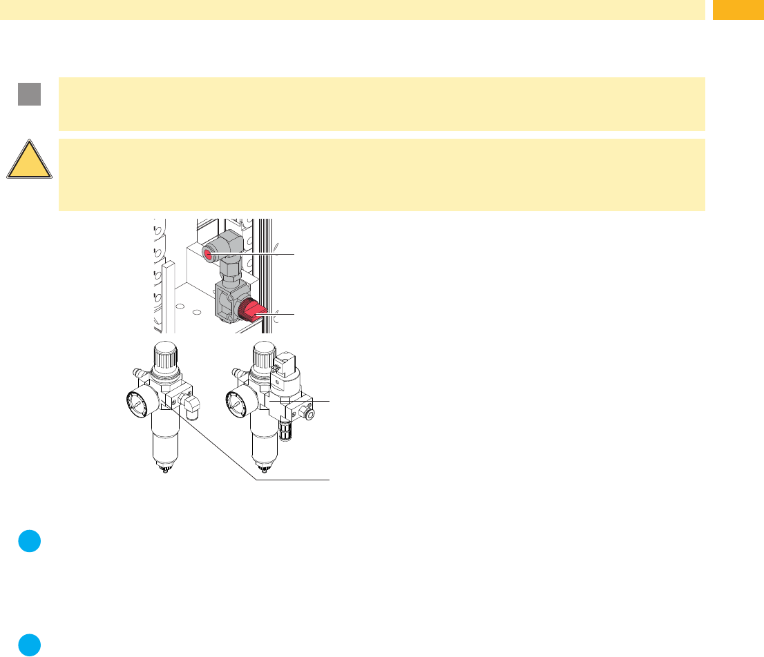
6.7 Connecting the Compressed Air
!
Attention!
Adjustments and function control where undertaken with a compressed air value of 4.5 bar.
The applicator operating range is between 4.0 and 6.0 bar.
!
Warning!
In case of connecting printer and compressed air the applicator is regard as in operation.
Do not reach into the zone of the moving pad and keep long hair, loose clothes, and jewelry away.
Danger of injury and damage by the moving rods!
2
1
3
4
1 Check the vertical position of the stop valve
(2). (The stop valve is closed in the picture.)
2 Attachthecompressedairviathetting(1).
3 Open the stop valve (2). (The lever indicates
thedirectionofairow.)
4 Switch on the printer.
It's possible to use an air pressure regulation unit
with included magnetic valve. *(3)
Controlling via the printer.
Interface description of the printer air pressure
regulation unit *(4)
Fig. 13 Compressed air connection
i
Note!
In case the pad is outside the starting position at the moment of switching on the air pressure the procedure
will be interrupted and an error message will be displayed.
By pushing the pause button on the printer the error is acknowledged and the pad will move back to its
starting position.
The Applicator is ready for work.
i
Note!
Only mount and use the air pressure regulation unit in the illustrated position or the functionality of the
air-water separator cannot be guaranteed.
20 20
7 Adjustments
7.1 Pad Adjustments
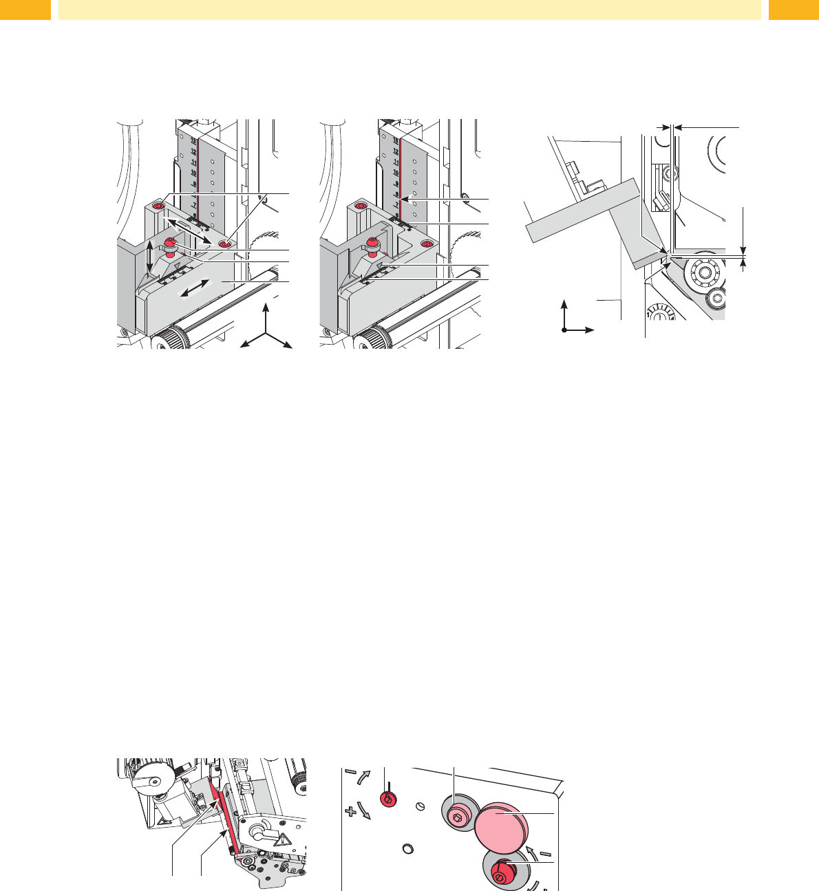
For optimal results it is necessary to place the pad precisely over the dispensed labels for the take over procedure.
Moving the pad in X-, Y- and Z-direction
10
1 mm
9
3
2
4
1
5
6
8
7
1 mm
y
x
z
x
y
z
Fig. 14 Moving the pad assembly
Adjustment in X-direction (sideways adjustment)
1. Loosen screw (3).
2. Move the cylinder assembly group (5) including pad along the cross beam until the pad is over the middle of the
label intended for application. For better orientation there is a graduation mark (7,8) depicted on the assembly
group.
3. Tighten screw (3).
Adjustment in Y-direction (print direction)
1. Loosen screw (1).
2. Move cylinder assembly (4) including pad along the guide rail so that the distance between the edge of the pad
(5) and the edge of the dispense plate (6) of the printer is approximately 1 mm. Graduation (5,6) can be used for
orientation.
3. Tighten screws (1).
Adjustment in Z-direction (height adjustment)
1. Loosen screw (3).
2. Turn setting screw (2) so that the bottom of the pad is 1 mm over the top edge of the dispense plate (6).
3. Tighten screw (3).
Adjusting the Parallelism between Pad and Dispense Edge
The edge of the pad must be parallel to the dispense edge of the printer.
9 10
14
13
11 12
Fig. 15 Adjusting the pad to the dispense edge
1. Loosen knurled screw (13) and screw (12).
2. Push the applicator against the printer and adjust the angle between applicator pad edge (9) and printer
dispensing plate (10) via the setting screw (14) and the eccentric (11).
3. Tightenscrew(12)andrextheapplicatorviaknurledscrew(13)oftheprinter.
21
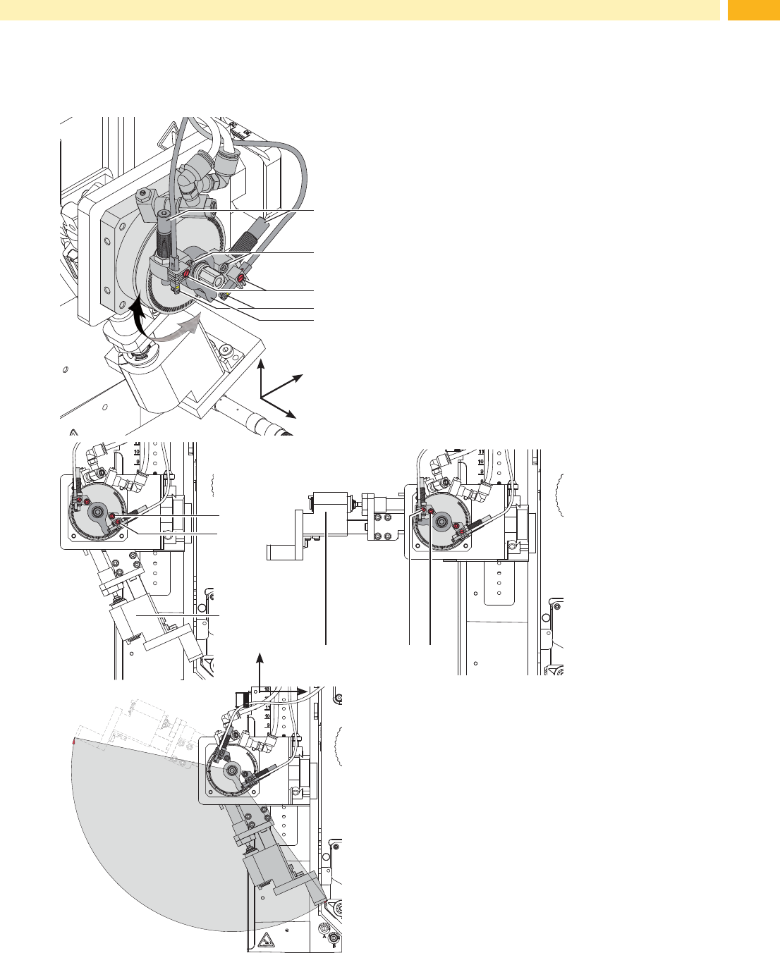
7.2 Adjusting the Swing Area of the Pad
Theswingareaofthepadassemblyandthusthelabellingpositionaresettoclientspecicationsbythefactory.In
case of changing the labelling position or the pad type is may be necessary to adjust the swing area (angle).
2
3
y
x
z
4
1
5
• Loosen screw (2).
• Turn the lever (6) with the stopper (3) in the desired
labelling position.
• Turn stopper with the sensor (1/4) so that the spring is
pushed in entirely.
• Tighten screw (2) .
• Loosen screw (3) and move the sensor (4) so that the
LED will lights up.
• Tighten screw (3) .
• Loosen nut of the stopper (1). Fine tune the setup by
turning the stopper (1) and tighten the nut to lock the
system in place.
• If necessary readjust sensor (4).
2
3
6
236
ca. 140°
Fig. 16 Adjusting the swing area of the pad
y
x
z
7 Adjustments