SA_3214_en.pdf - 第22页
22 22 7.3 Stopper for Operation Mode "Blow on" In order to label a product without physically coming into contact with it use the "blow on" mode. The stopper (1) will limit the downward movement of th…
21
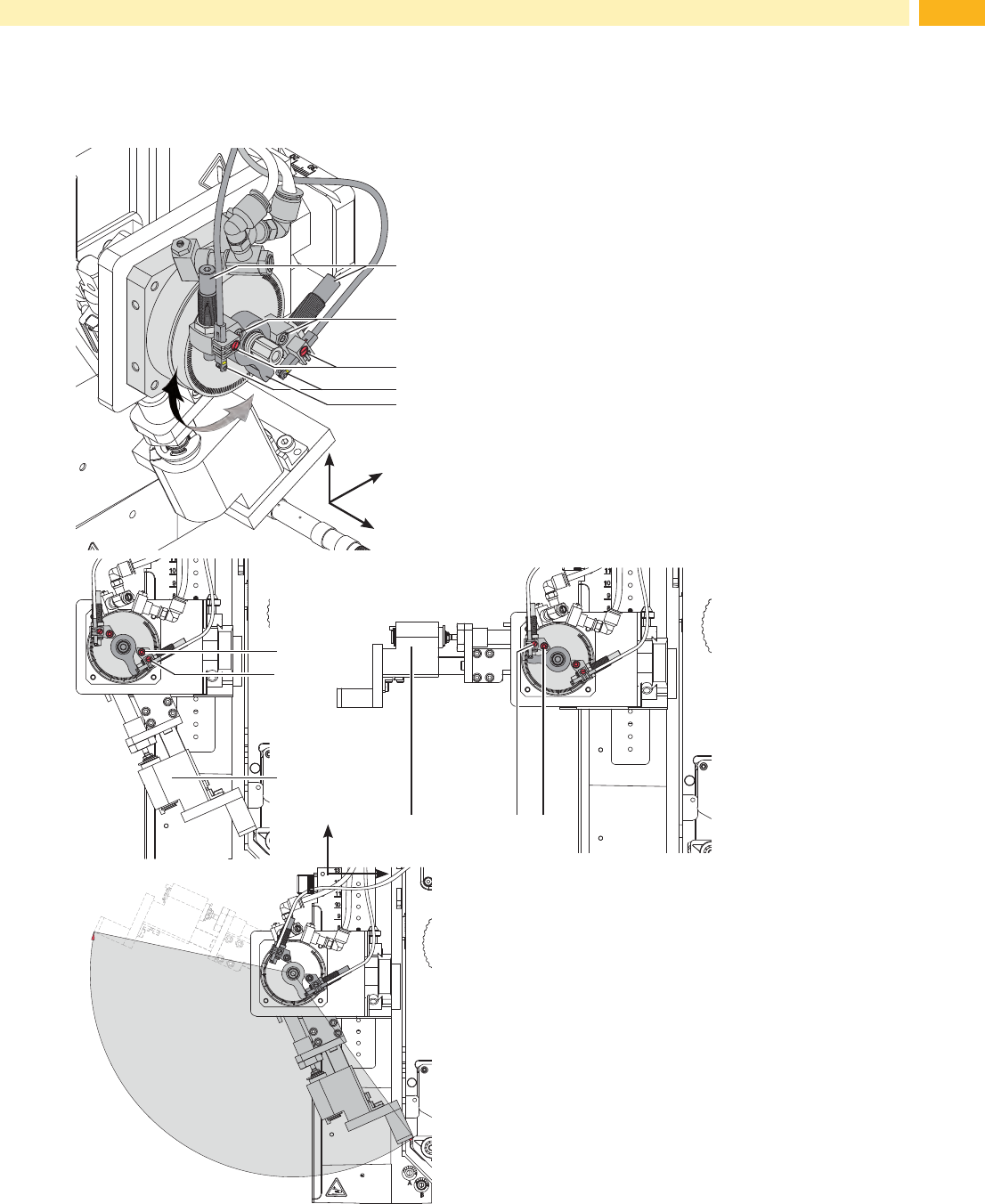
7.2 Adjusting the Swing Area of the Pad
Theswingareaofthepadassemblyandthusthelabellingpositionaresettoclientspecicationsbythefactory.In
case of changing the labelling position or the pad type is may be necessary to adjust the swing area (angle).
2
3
y
x
z
4
1
5
• Loosen screw (2).
• Turn the lever (6) with the stopper (3) in the desired
labelling position.
• Turn stopper with the sensor (1/4) so that the spring is
pushed in entirely.
• Tighten screw (2) .
• Loosen screw (3) and move the sensor (4) so that the
LED will lights up.
• Tighten screw (3) .
• Loosen nut of the stopper (1). Fine tune the setup by
turning the stopper (1) and tighten the nut to lock the
system in place.
• If necessary readjust sensor (4).
2
3
6
236
ca. 140°
Fig. 16 Adjusting the swing area of the pad
y
x
z
7 Adjustments
22 22
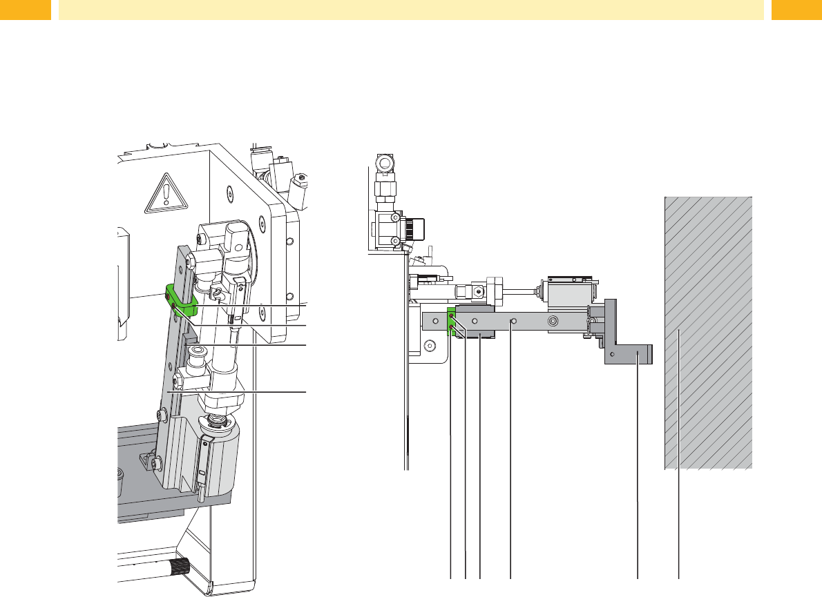
7.3 Stopper for Operation Mode "Blow on"
In order to label a product without physically coming into contact with it use the "blow on" mode. The stopper (1) will
limit the downward movement of the cylinder and prevent contact with the product.
1
1
3
2
2 5 64
4
3
Fig. 17 Adjust the stopper in the operation mode "blow"
1. Turn off the air pressure.
2. Remove the tubes from the throttle valves of the swing-, extension- and lift- cylinder.
3. Loosen the screws (2) on the stopper (1).
4. Place the product (6) in the position it is to be labeled in.
5. Swing the pivot arm to the stopper manully. This pivot cylinder is adjusted according to 4.1.5.
6. Pull the pad assembly (5) toward the product until the distance between pad (5) and the product (6) is a maximum
of 10 mm apart.
7. Move the stopper (1) along the rail (4) to the carriage (3) and tighten screws (2).
8. Reconnect the tubes into the throttle valves and pivot out the swing cylinder as well as the lift cylinder again.
7 Adjustments
23
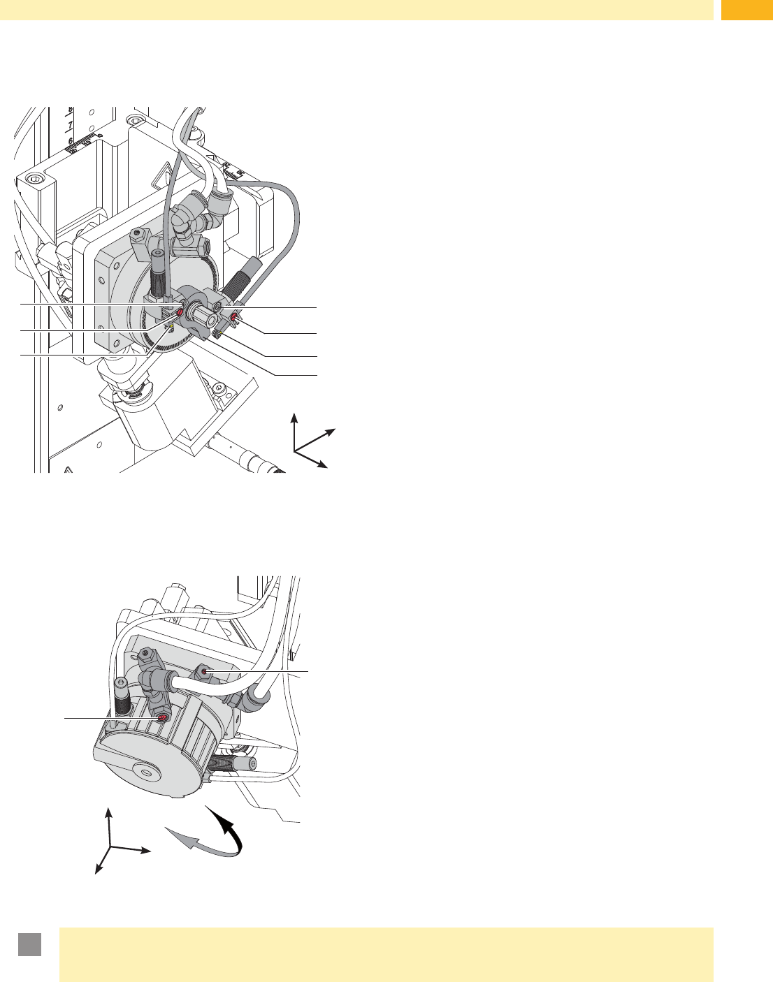
7.4 Adjusting the Sensors of the Swing Drive
4
5
y
x
z
1
2
3
6
7
Disconnect the pressure air.
Switch on the printer.
The sensors (3 and 6) detect the arrival of the end position of
the swing lever. The generated signals are necessary for the
following processes.
- When the sensor (6) is triggered in the start position the
printing and application process can begin.
- When the sensor (3) is triggered the in the rotated position
cylinder Z can be extended to start the procedure to
stamp the label onto the product.
Turn and hold the pad assembly into the needed end
position.
Loosen screw (2 or 5) .
Move the sensor (3 or 6) so that the sensor will be securly
triggered by the stopper (7) .
Secure triggering is recognizable by the lit up LED on the
sensor.
As soon as the assembly group leaves the extended
position the sensor should untrigger. This is made visible
by the LED switching off.
Tighten the appropreate screw (2 or 5) .
Fig. 18 Adjusting the sensors of the swing drive
7.5 Adjusting the Speed of the Swing Drive
2
y
x
z
1
A
B
The speed of the swing drive is controlled by air throttle
valves. Towards the end of the swing movement the arm is
slowed by the damper (3). If the dampening is too strong and
the swing arm cannot reach the its end position to trigger
the sensors and ERROR message will be displayed and the
process is interrupted.
To increase the swing out speed turn the screw (1)
counterclockwise. Swing movement in direction to B.
To reduce the swing out speed turn the screw (1)
clockwise. Swing movement in direction to B.
To increase the swing in speed turn the screw (2) counter-
clockwise. Swing movement in direction to A.
To reduce the swing in speed turn the screw (2) clockwise.
Swing movement in direction to A.
Fig. 19 Throttle valves on the swing drive
!
Attention!
The time for the downward movement of the pad may not exceed 2 seconds
Otherwise the error message "Lower position" will appear.
7 Adjustments