SA_3214_en.pdf - 第18页
18 18 6 Installation 6.5 Mounting the Pad 2 7 3 4 8 6 5 1 4 Fig. 1 1 Mounting the pad 1. Slide the pad with the holes (4) onto the pad holder (1) via the pins (3). 2. Fasten the pad to the pad holder (1) with the screw (…
17
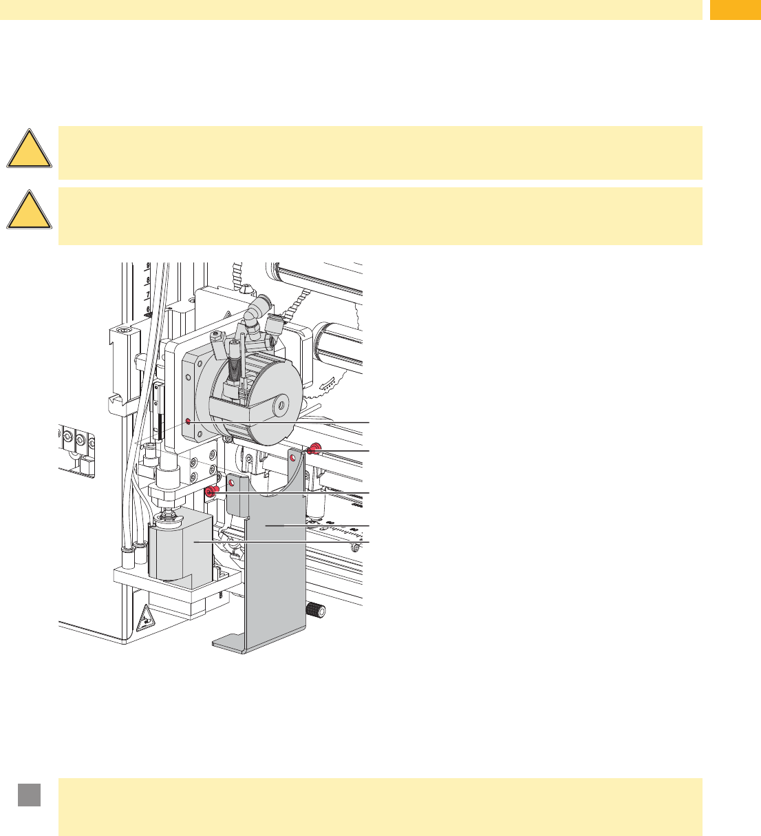
6.4 Transport lock
The transportation lock of the applicator prevents movement of the applicators parts to avoid damage and ensure
safe transportation for the applicator and the persons executing it.
!
Warning!
Ensure that the printer's power supply is disconnected and the compressed air supply is closed before
dismounting the applicator.
!
Warning!
Risk of injury and damage in the case of incorrect use and/or operation of the devices.
The applicator may only be used with a Hermes+ series printer.
2
3
2
1
4
Fig. 10 Transport lock
Remove the transport lock
1. Loosen screws (2) of the transport lock (3) .
2. Remove the transport lock (3).
!
Attention!
Mount the transportation lock for every transport.
Keep the transport lock and the screws.
Mounting the transport lock
1. Turn the swing arm (4) so that the pad holder is in the cut-out of the transport lock (3) .
This is an almost vertical position.
2. Place the transport lock (3) so that the holes in the transport lock (3) are over the holes (1) on both sides of the
swing cylinder socket.
3. Tighten screws (2).
6 Installation
18 18
6 Installation
6.5 Mounting the Pad
2
7
3
4
8
6
5
1
4
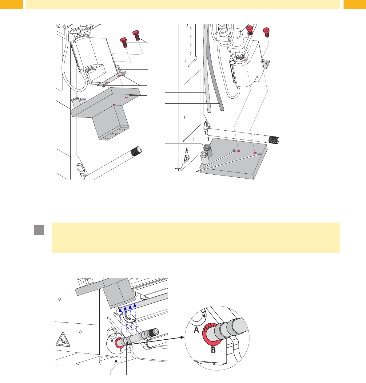
Fig. 11 Mounting the pad
1. Slide the pad with the holes (4) onto the pad holder (1) via the pins (3).
2. Fasten the pad to the pad holder (1) with the screw (2).
3. Insertthevacuumtube(5)andthesupportairtube(6)intotheappropriatepush-in-ttings(7,8)ofthepad.
!
Attention!
To avoid possible collisions of the pad with other parts of the printer-applicator system, please roughly
align the pad in all directions ( Adjustments) before connecting the applicator to the compressed air
supply!
6.6 Mounting the Blow Tube
1
2 3
Fig. 12 Mounting the blow tube
The blow tube (3) for the supporting air can be rotated around its axis. This allows the direction of the supporting air
to be optimized.
1. Loosen screw (1).
2. Put the blow tube (3) into the hole A (2) as far as possible.
3. Tighten screw (1). Adjust the blow tube (Support air)
19
6 Installation
6.7 Connecting the Compressed Air
!
Attention!
Adjustments and function control where undertaken with a compressed air value of 4.5 bar.
The applicator operating range is between 4.0 and 6.0 bar.
!
Warning!
In case of connecting printer and compressed air the applicator is regard as in operation.
Do not reach into the zone of the moving pad and keep long hair, loose clothes, and jewelry away.
Danger of injury and damage by the moving rods!
2
1
3
4
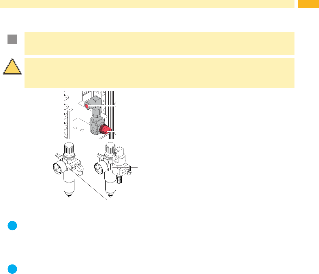
1 Check the vertical position of the stop valve
(2). (The stop valve is closed in the picture.)
2 Attachthecompressedairviathetting(1).
3 Open the stop valve (2). (The lever indicates
thedirectionofairow.)
4 Switch on the printer.
It's possible to use an air pressure regulation unit
with included magnetic valve. *(3)
Controlling via the printer.
Interface description of the printer air pressure
regulation unit *(4)
Fig. 13 Compressed air connection
i
Note!
In case the pad is outside the starting position at the moment of switching on the air pressure the procedure
will be interrupted and an error message will be displayed.
By pushing the pause button on the printer the error is acknowledged and the pad will move back to its
starting position.
The Applicator is ready for work.
i
Note!
Only mount and use the air pressure regulation unit in the illustrated position or the functionality of the
air-water separator cannot be guaranteed.