SA_3214_en.pdf - 第27页
27 7 Adjustments 7.10 Blow T ube ( Support Air) Adjustments For an optimal take up of the label by the applicator set the supporting air so that the entire label is constantly , without turbulence, blown onto the pad. Al…
26 26
7 Adjustments
7.9 Vacuum Adjustments
Thelabelwillbexedtothepadbyavacuumthatneedstobestrongenoughtoholdthelabelontothepadwhilenot
hindering the label on its way from the printer to the pad this is also dependant on the label material being used.
The label should cover all the suction holes of the pad.
The standard factory value of the vacuum of the pad is -0.6 bar.
i
Note!
By adjusting the vacuum of the pad the transportation of the label from the dispensing edge to the pad will
be affected.
If the vacuum is too strong the label will not reach the intended position on the pad.
support air
vacuum
1
Fig. 23 Throttle valve "vacuum"
Adjust the vacuum with the throttle valve "vacuum" (1) so that the label is sucked onto the pad over the entire
area of the label.
To increase the vacuum turn the setting screw of the throttle valve (1) counterclockwise.
Measuring Point Vacuum (MP V).
RP V
1
2
3
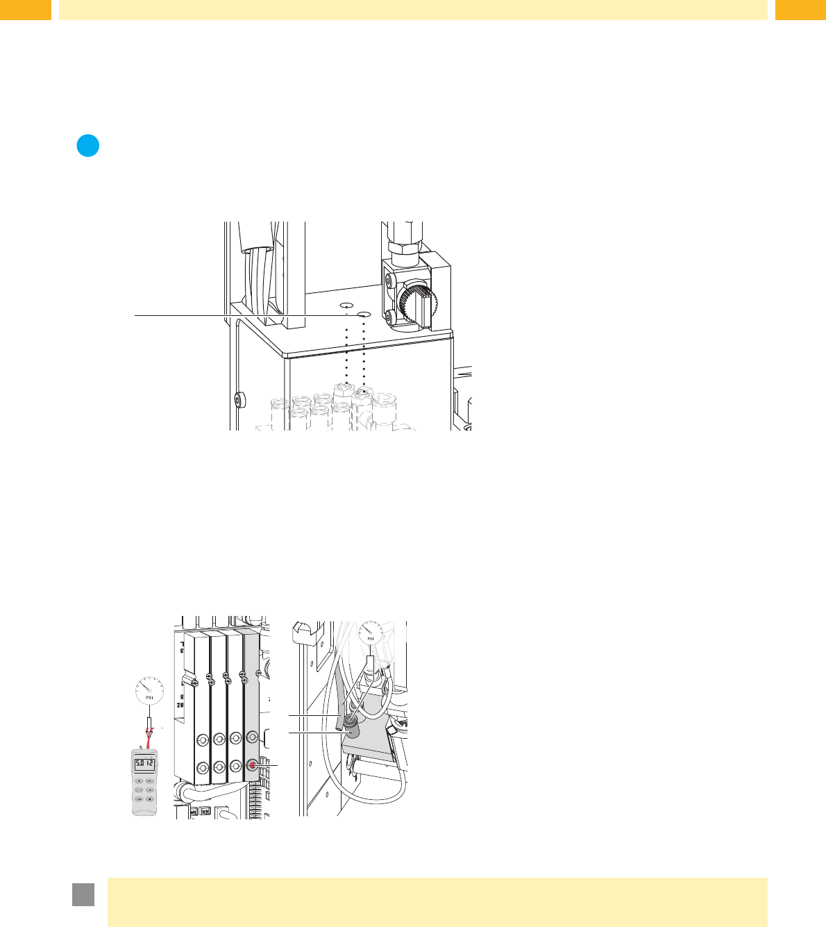
Fig. 24 Measure the vacuum
Use a manometer with a measuring range of -7 to 7 bar.
MP V: Vacuum (default value -0.6 bar)
1. Remove the cover.
2. Cover the suction plate hermetically.
3. Attach the manometer to the MP V.
- Tube (1) at the energy track
- Fitting (2) of the pad
4. Activate the valve manually by pressing the micro switch
(3) while the compressed air is switched on.
5. Adjust the vacuum via the throttle valve "vacuum" as
required.
6. Remount the cover.
!
Attention!
After pressure measurements, connect all component exactly and check it.
27
7 Adjustments
7.10 Blow Tube (Support Air) Adjustments
For an optimal take up of the label by the applicator set the supporting air so that the entire label is constantly, without
turbulence, blown onto the pad.
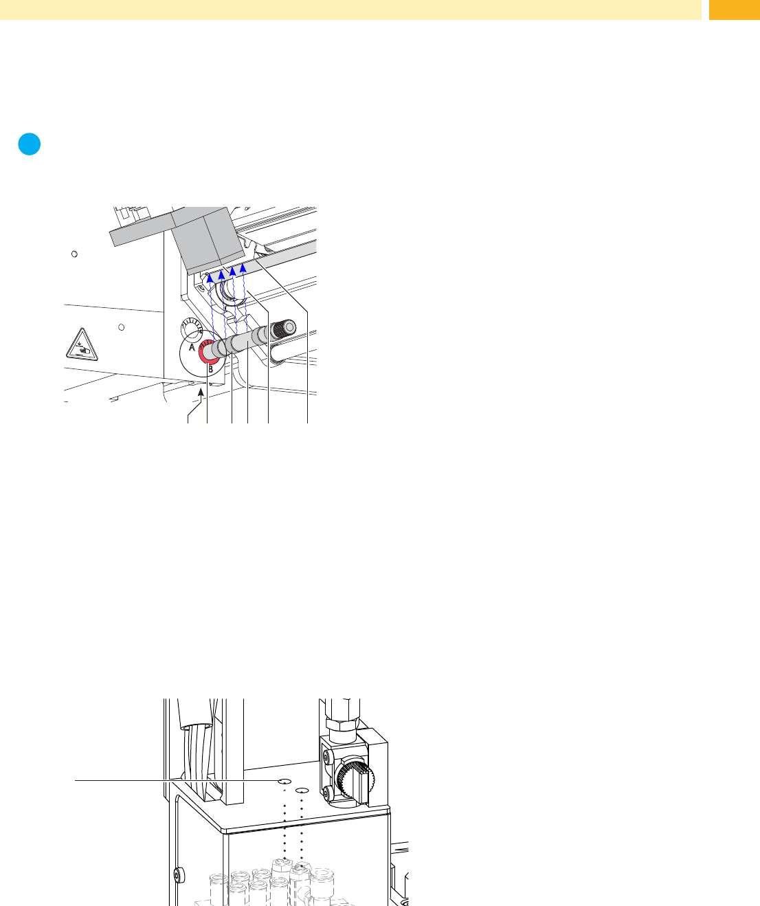
All holes in the blow tube that exceed the width of the label should be covered by a rubber ring (3).
The factory default air pressure of the blow tube is 2 bar.
i
Note!
If the breadth of the printer is changed (2", 4" or 6") the appropriate blow tube should be used. When
changingthelabelwidthcheckthenumberofcoveredholesoftheblowtubeandreconguretheblowtube
settings.
1
2 3
5
6
4
Fig. 25 Adjust the blow tube
The blow tube (4) for the supporting air can be rotated around its axis. That way the direction of the supporting air can
be optimized.
1. Loosen screw (1).
2. Place the blow tube (4) into the tube adapter B (2).
Turn the blow tube (2) in the direction that supports the uptake of the label from the dispensing edge (6) to the
pad (5).
Turn the blow tube (2) in that direction, that the air current supports the sucking of the label from the dispense
edge (6) by the pad (5).
• For smaller labels direct the air current to the dispense edge (5) of the printer.
• For larger labels direct the air current away from the dispense edge (6) .
Use the graduation for orientation.
3. Tighten screw (1).
support air
vacuum
1
Fig. 26 Throttle valve "support air"
The throttle valve (1) enables the variation of the supporting air for optimizing the label take up procedure.
To increase the strength of the supporting air turn the screw of the valve (1) counterclockwise.
28 28
7 Adjustments
Measuring Point Support Air (MP S)
3
2
1
RP S
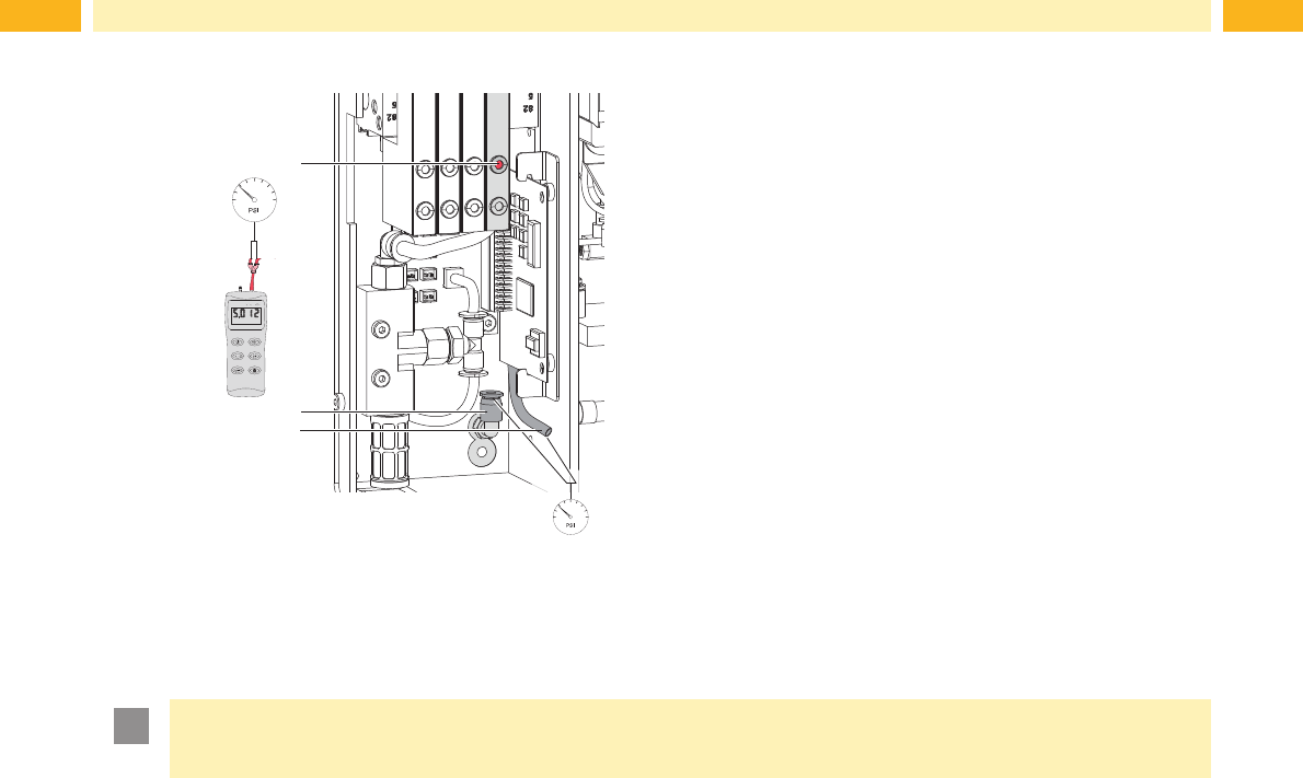
Use a manometer with a measuring range of -7 to 7 bar.
MP S: Support Air (default value 2 bar)
1. Remove cover and connect the manometer to the MP S.
- Tube (3) from valve block to blow tube connector.
- Fitting (2) on the blow tube.
2. While the compressed air is connected, push the micro
switch (1) to measure the pressure.
3. Adjust the strength of the "support air" via the corre-
sponding throttle valve.
4. Remount the cover.
Fig. 27 Measuring points for support air.
!
Attention!
After pressure measurements have concluded reconnect and recheck all the tubes.