SA_3214_en.pdf - 第24页
24 24 7 Adjustments 7.6 Sensors on Cylinder Z 1 2 5 4 3 Fig. 20 Sensors on cylinder Z Sensor Start Position 1 1. Loosen screw (1) on sensor (3) "Start Position" and move the sensor so that the top edge of the s…
23
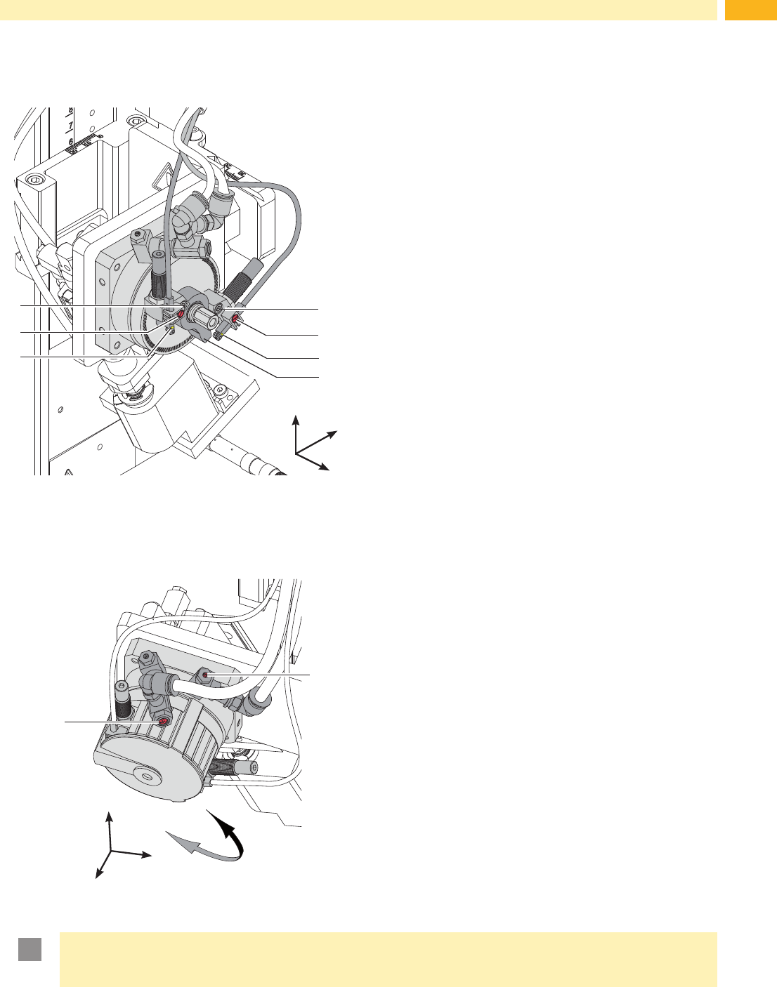
7.4 Adjusting the Sensors of the Swing Drive
4
5
y
x
z
1
2
3
6
7
Disconnect the pressure air.
Switch on the printer.
The sensors (3 and 6) detect the arrival of the end position of
the swing lever. The generated signals are necessary for the
following processes.
- When the sensor (6) is triggered in the start position the
printing and application process can begin.
- When the sensor (3) is triggered the in the rotated position
cylinder Z can be extended to start the procedure to
stamp the label onto the product.
Turn and hold the pad assembly into the needed end
position.
Loosen screw (2 or 5) .
Move the sensor (3 or 6) so that the sensor will be securly
triggered by the stopper (7) .
Secure triggering is recognizable by the lit up LED on the
sensor.
As soon as the assembly group leaves the extended
position the sensor should untrigger. This is made visible
by the LED switching off.
Tighten the appropreate screw (2 or 5) .
Fig. 18 Adjusting the sensors of the swing drive
7.5 Adjusting the Speed of the Swing Drive
2
y
x
z
1
A
B
The speed of the swing drive is controlled by air throttle
valves. Towards the end of the swing movement the arm is
slowed by the damper (3). If the dampening is too strong and
the swing arm cannot reach the its end position to trigger
the sensors and ERROR message will be displayed and the
process is interrupted.
To increase the swing out speed turn the screw (1)
counterclockwise. Swing movement in direction to B.
To reduce the swing out speed turn the screw (1)
clockwise. Swing movement in direction to B.
To increase the swing in speed turn the screw (2) counter-
clockwise. Swing movement in direction to A.
To reduce the swing in speed turn the screw (2) clockwise.
Swing movement in direction to A.
Fig. 19 Throttle valves on the swing drive
!
Attention!
The time for the downward movement of the pad may not exceed 2 seconds
Otherwise the error message "Lower position" will appear.
7 Adjustments
24 24
7 Adjustments
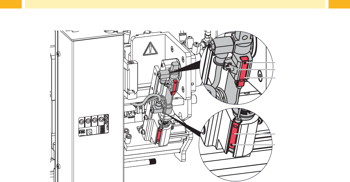
7.6 Sensors on Cylinder Z
1
2
5
4
3
Fig. 20 Sensors on cylinder Z
Sensor Start Position 1
1. Loosen screw (1) on sensor (3) "Start Position" and move the sensor so that the top edge of the sensor is on the
samelevelasthesensorholderandtscomfortablyintoit.
2. Close the compressed air supply and pull out the tubes from cylinder-Z. Switch on the printer with an existing
connection to the applicator via the electronic interface (SUB-D).
3. Manually move the pad to the top of the stopper.
4. Loosen screw (2) on the sensor holder.
5. Move the sensor so that the LED lights up when the cylinder is completely contracted. A distance of 10 mm
between the top edge of the sensor and the lower edge of the connecting ring of cylinder is required as illustrated
inthegureabove.
6. Tighten screw (2).
Labelling Sensor 2
The position of the labelling sensor (6) is dependant on the pad assembly's weight and the angle of the mounting
position. The triggering magnet is integrated into the adapter bolt.
1. Bring the printer and applicator into their intended operational position.
2. Swing the pad in the labelling position.
3. Loosen screw (5) and move the sensor (4) so that it triggers and the LED lights up when the adapter bold is
driven into the tamp assembly group.
4. Tighten screw (5).
25
7 Adjustments
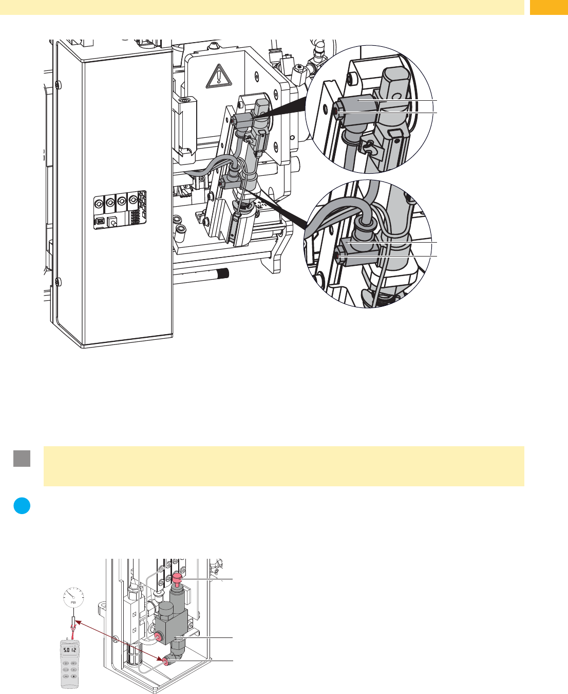
7.7 Lift Speed of Cylinder Z
1
2
4
3
Fig. 21 Throttle valves on the cylinder Z
The speed of the pad movement can be regulated via two throttle valves (1 and 3).
Adjust the pad movement speed as necessary.
To increase the downward speed turn the screw (4) at the lower valve (3) counterclockwise.
To increase the upward speed turn the screw (2) at the upper valve (1) counterclockwise.
!
Attention!
The time for the downward movement of the pad may not exceed 2 seconds
Otherwise the error message "Lower position" will appear.
i
Note!
To reduce the air pressure in Z-direction an optional pressure reduction valve (5) is available.
7.8 Adjusting the pressure reduction valve
7.8 Adjusting the pressure reduction valve
3
2
1
MP S
1
2
3
The pressure reduction valve (2) will when labelling pressure-
sensitive products or to increase generally safety by reducing
the pressure of the cylinder in Z-direction.
The standard value is 2.5 bar.
Connect the manometer between tube and exit (3) and
adjust the pressure to 2.5 bar via knurled screw (1).
It is possible to upgrade to the pressure reduction as a set
order with instructions, or as an integrated part of the default
factory order.
Fig. 22 Pressure reduction valve Cylinder Z