SA_3214_en.pdf - 第7页
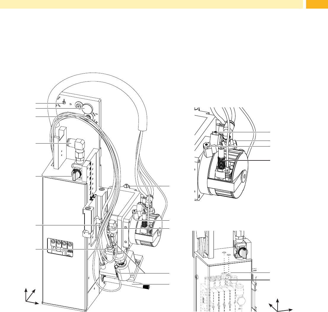
7 2.3 Overview support air vacuum 17 18 12 11 7 6 5 4 2 8 10 3 1 9 13 14 15 16 Fig. 2 Device overview - front view 1 Eccentric o adjust the angle between applicator and printer 2 Knurled screw for attaching the applicato…

6 6
2 Product Description
2.1 Important Features
• The supporting air and the vacuum as well as the speed of the cylinder are adjustable. That way the applicator
can be adapted to different label materials and sizes.
• To avoid contamination within the vacuum channels they are cleaned by air pressure impulse at the end of each
application.
• For operation in a system the I/O interface of the printer can be used.
2.2 Technical Data
Label transfer method Tamp pad Tamp pad
with foam
Tamp pad
with label stop
Blow pad
3214 L/R 11 F 3214 L/R 12 F 3214 L/R 61 F 3214 L/R 2100
Label width in mm for Hermes
+
4 4 -58 10 - 58 10 - 58 10 - 58
for Hermes
+
6 10 - 114 10 - 114 10 - 114 10 - 80
Label height in mm 5 - 80 10 - 80 5 - 80 10 - 80
Compressed air pressure 0.45 MPa (4.5 bar)
Sound pressure level under 74 dB(A)
Product during
labeling
xed
¢ ¢ ¢ ¢
in motion - - -
¢
Labeling onto the
product
sideways
¢ ¢ ¢ ¢
Product height x
¢ ¢ ¢ ¢
Distance of product to
dispensing edge in mm
250 - 280 250 - 280 250 - 280 250 - 280
Horizontal short stroke cylinder in mm 5 - 30 5 - 30 5 - 30 5 - 30
Swing angle 45° - 95° 45° - 95° 45° - 95° 45° - 95°
Immersion depth pad F
2)
up to mm 30 30 30 -
Cycle time about frequency/min.
1)
25 25 25 25
1)
Determined at 100 mm stroke below device / smallest label height / print speed 100 mm/s .
2)
Immersion depth at applicator >25 mm, the cover of the Hermes
+
mustbemodied.
Table 1 Technical Data
7
2.3 Overview
support air
vacuum
17
18
12
11
7
6
5
4
2
8
10
3
1
9
13
14
15
16
Fig. 2 Device overview - front view
1 Eccentric o adjust the angle between applicator and
printer
2 Knurled screw for attaching the applicator to the
printer
3 Setting screw to adjust the angle between applicator
and printer
4 Compressed air connector
5 Shutoff valve
6 Throttle valve cylinder - move in Z-direction
7 Throttle valve cylinder - move out Z-direction
8 Setting screw for vertical adjustment cylinder
assembly
9 Swing drive
10 Cylinder - Z-direction
11 Sensor labeling position
12 Blow tube for supporting air
13 Throttle valve swing drive - swing in
14 Throttle valve swing drive - swing in
15 Throttle valve swing drive - swing out
16 Setting screw to adjust the angle of the swing area
17 Support air throttle valve
18 Vacuum throttle valve
Front view
Throttle valves vacuum/support air
y
x
z
2 Product Description
Swing drive
y
x
z
8 8
22
21
20
23
Rear view
19
19
24
25
26
27
28
30
29
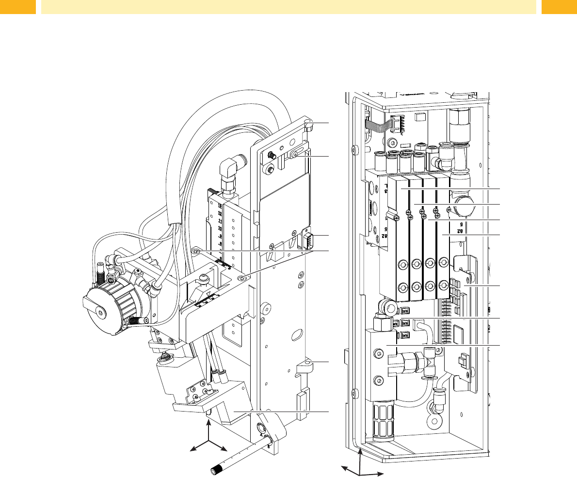
Fig. 3 Device overview - rear view Fig. 4 Device overview - control system
19 Hinges
20 Locking for hinges
21 Interface to the printer
22ScrewstoxtheZ-direction
23 Pad (customized)
24 Valve swing drive
25 Valve Cylinder Z/Y-direction
26 Valve Blow air
27 Valve Vacuum and Support air
28 PCB Applicator Control
2 Product Description
yx
z
Valves and control system
y
x
z