00196433-02_AI_Vakuumpumpe_X-Serie_70XDE+EN.pdf - 第117页
Assembly instructions: Vacuum pump for SIPLACE X-series 04/2009 Edition 117 Fig. 2.9 - 6 C&P20 with cover f or the v acuum : Screw the cover (03046347-) han d-tight onto the “orifice ri ng C&P20”. 2
Assembly instructions: Vacuum pump for SIPLACE X-series
04/2009 Edition
116
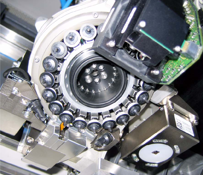
: Now screw the orifice ring tight all around the edge using the “DIN 912-M3 x10” screws. Make
sure that it is not tilted at all.
: Check that the “O-ring 42x2 NBR70” is placed correctly in the
groove of the orifice ring.
Fig. 2.9 - 5 C&P20 with orifice ring C&P 20 (03046344-)
Assembly instructions: Vacuum pump for SIPLACE X-series
04/2009 Edition
117
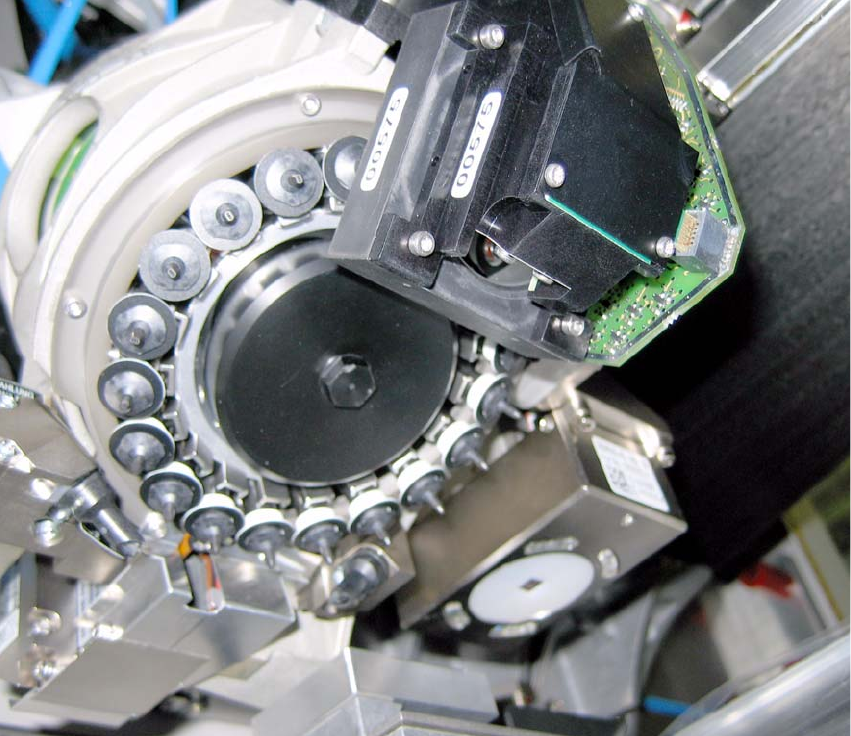
Fig. 2.9 - 6 C&P20 with cover for the vacuum
: Screw the cover (03046347-) hand-tight onto the “orifice ring C&P20”.
2
Assembly instructions: Vacuum pump for SIPLACE X-series
04/2009 Edition
118
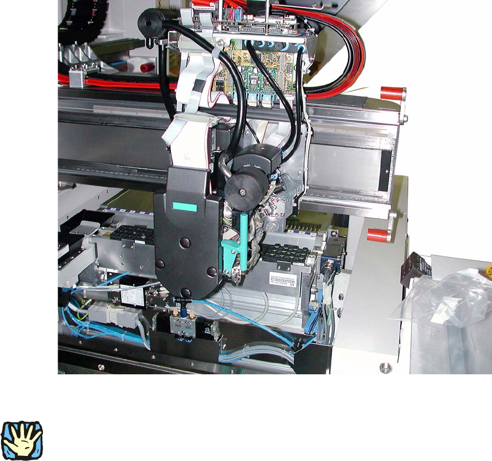
2.10 Converting the C&P 6/12
Fig. 2.10 - 1 C&P12 with compressed air (initial state)
2
2
BEFORE starting any work, shut down the operating system correctly, then switch the machine
OFF at the main power switch and disconnect from the main power supply. In addition, the com-
pressed air supply must be switched off at the compressed a
ir unit's main valve in the machine
base and vented by actuating the needle valve on the compressed air unit.
2