00196433-02_AI_Vakuumpumpe_X-Serie_70XDE+EN.pdf - 第95页
V ersion 2, mount for vac. connection X, complete ( item no.: 03075466-xx ) 2 Assembly instructions: Vacuum pump for SIPLACE X-series 04/2009 Edition 95 2 2 : Attach the hose s to the gantries. 2 With QuadLane, the distr…
Assembly instructions: Vacuum pump for SIPLACE X-series
04/2009 Edition
94
2
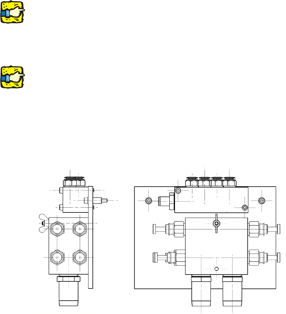
We recommend that you connect the “Suction and pressure hose Di 32 HELISPRING” (item no.:
00368279-) for the vacuum pump to the vacuum distributor before you fit the distributor, and then
fix the hose using “Hose clip DIN 3017 NW 32 - 50” (item no.: 00363127-). 2
2
: Screw the air distributor to the side wall of the compressed air supply (1 screw).
Use a ratchet screwdriver with a short bit or a hexagon socket spanner.
2
With some machine serial numbers it may be necessary to fit the vacuum distributor on an addi-
tional plate.
The existing cooling air distributor must then be detached in order to fit this plate.
The plate for the vacuum distributor is then screwed to th
e machine together with the cooling air
distributor. 2
2
: Fix the vacuum distributor block to the plate using the two screws (00845068-, DIN912, M6x70-
8.8).
Version 1, angled vac. connection 03038058, complete (item no.: 03075301-xx) 2
2
2
2
2
2
Version 2, mount for vac. connection X, complete (item no.: 03075466-xx) 2
Assembly instructions: Vacuum pump for SIPLACE X-series
04/2009 Edition
95
2
2
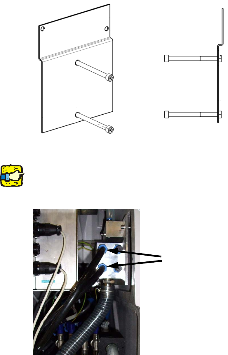
: Attach the hoses to the gantries.
2
With QuadLane, the distributor for the SMEMA interfaces is installed at the same installation lo-
cation.
It is therefore a good idea to use the two left-hand connections to supply the gantry. In this case,
the two righ
t-hand connections should be closed with plugs. 2
Hoses to the gantries
2
Assembly instructions: Vacuum pump for SIPLACE X-series
04/2009 Edition
96
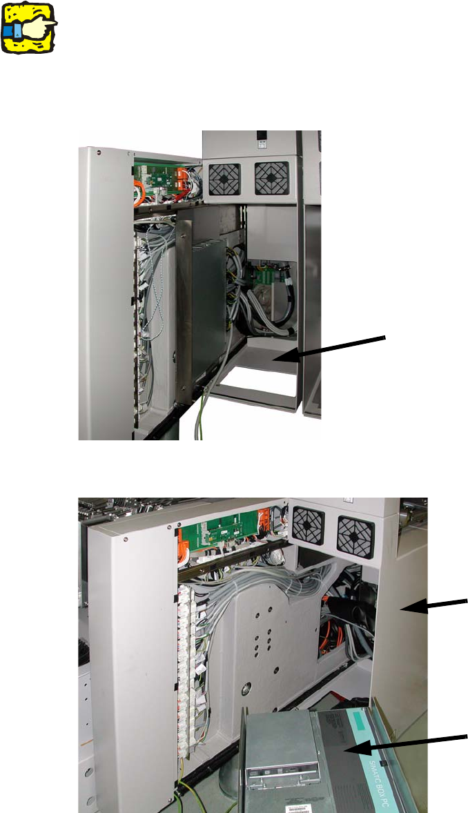
2.8.4 Connecting the vacuum pump controller
2
The cable is already installed on machines from serial number E-001. 2
2
: Open the covers on the extension kits at locations 2 and 4.
: At location 2,
pull out the drawer unit for the 30V DC/DC converter for the component feeding.
Extension kit at location 2
2
: At location 4, pull out the computer unit.
Extension kit at location 4
Computer unit
2