00196433-02_AI_Vakuumpumpe_X-Serie_70XDE+EN.pdf - 第93页
Assembly instructions: Vacuum pump for SIPLACE X-series 04/2009 Edition 93 : Close of f any remaining free openings in the vacuum distributor block (with bl anking plug Q03051739-, pl ug QSC 16H). : Close the connections…
Assembly instructions: Vacuum pump for SIPLACE X-series
04/2009 Edition
92
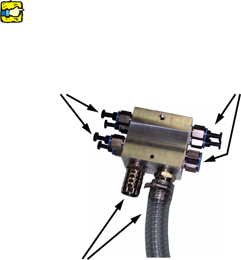
: Insert the (black) vacuum hoses into the plug-in connectors that are now free (see Fig. 2.8 - 17
and Fig. 2.8 - 19).
03015210-
Plug QSC-12H
03051739-
Plug QSC 16H
Fig. 2.8 - 19 Converted pneumatic distributor
Vacuum hoses from the vacuum distributor block to the gantry hoses (example for a 2-gantry placement machine)
2
Example for a 2-gantry placement machine:
Here there are now 2 gantries connected to the vacuum (black hoses). 2
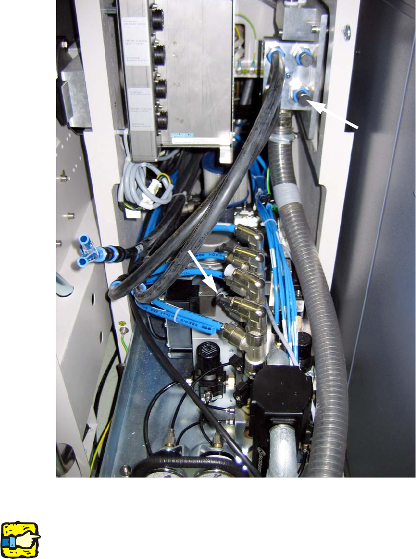
: Connect the vacuum hose to the vacuum d
istributor block (see Fig. 2.8 - 19).
Assembly instructions: Vacuum pump for SIPLACE X-series
04/2009 Edition
93
: Close off any remaining free openings in the vacuum distributor block (with blanking plug
Q03051739-, plug QSC 16H).
: Close the connections in the pneumatic unit that are now open using blanking plugs QSC-12H.
2
: The stop valve must not be closed, otherwise the compressed air supply needed for the place-
ment or reject circuit will be interrupted.
2
: Attach the compressed air hose to the distributor.
Connections for supplying the gantry
Connecting hose, vacuum pump X
(item no.: 03075872-xx)
Vacuum pump 2 2
Connections for supplying the gantry
Connecting hose, vacuum pump X
(item no.: 03075872-xx)
Vacuum pump 1 2
Connections for vacuum pumps
One vacuum pump can supply one or
two C&P20 placement heads. 2
2
2
2
2
2
Assembly instructions: Vacuum pump for SIPLACE X-series
04/2009 Edition
94
2
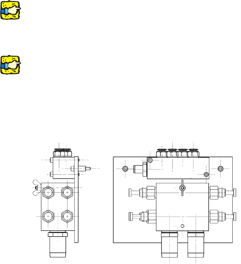
We recommend that you connect the “Suction and pressure hose Di 32 HELISPRING” (item no.:
00368279-) for the vacuum pump to the vacuum distributor before you fit the distributor, and then
fix the hose using “Hose clip DIN 3017 NW 32 - 50” (item no.: 00363127-). 2
2
: Screw the air distributor to the side wall of the compressed air supply (1 screw).
Use a ratchet screwdriver with a short bit or a hexagon socket spanner.
2
With some machine serial numbers it may be necessary to fit the vacuum distributor on an addi-
tional plate.
The existing cooling air distributor must then be detached in order to fit this plate.
The plate for the vacuum distributor is then screwed to th
e machine together with the cooling air
distributor. 2
2
: Fix the vacuum distributor block to the plate using the two screws (00845068-, DIN912, M6x70-
8.8).
Version 1, angled vac. connection 03038058, complete (item no.: 03075301-xx) 2
2
2
2
2
2