00196433-02_AI_Vakuumpumpe_X-Serie_70XDE+EN.pdf - 第124页
Assembly instructions: Vacuum pump for SIPLACE X-se ries 04/2009 Edition 124 Fig. 2.11 - 3 Correct the holding circuit v acuum v alue In mixed mode with C&P20 and C&P6/1 2 heads, there should be a vacuum of at le…
Assembly instructions: Vacuum pump for SIPLACE X-series
04/2009 Edition
123
2
The change to the machine database must only be carried out by SIPLACE Service. 2
2
2
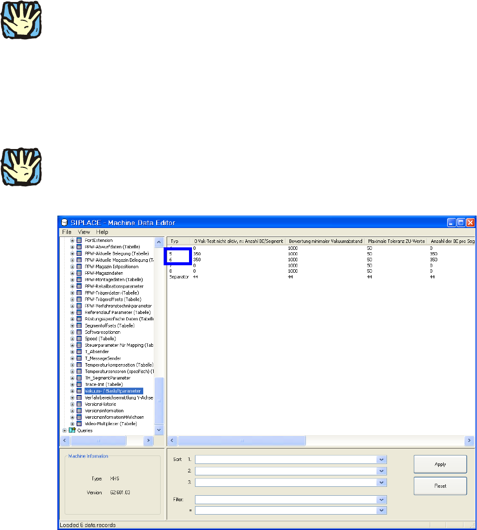
: Select the “Vacuum / Air blast parameters“ table from the database (see Fig. 2.11 - 2).
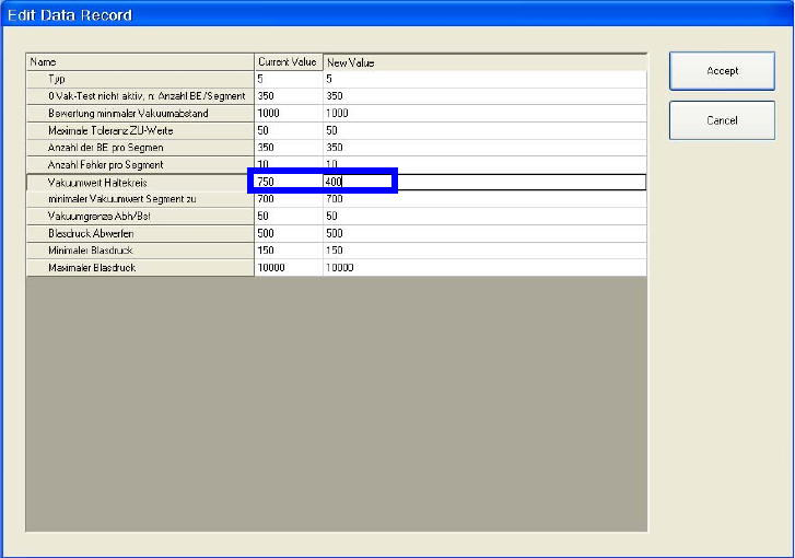
: Switch to Edit mode fo
r head types 5 and 6.
: Change “Vacuum value for holding circuit“ from 750 to 400 (see Fig.
2.11 - 3).
2
2
This data will be overwritten if the software is updated or if the MC distributor is used. It will then
have to be reedited. 2
2
2
Fig. 2.11 - 2 Select the Vacuum / Air blast parameters table
2
Assembly instructions: Vacuum pump for SIPLACE X-series
04/2009 Edition
124
Fig. 2.11 - 3 Correct the holding circuit vacuum value
In mixed mode with C&P20 and C&P6/12 heads, there should be a vacuum of at least -500 mbar
(for very large nozzles 920) to -600 mbar (for very small nozzles 906) at each placement machine/
head depending on the nozzle configuration. 2
If only C&P6/12 heads are used, the higher vacu
um of -600 mbar is normally achieved, since no
air leaks out due to the closed valves (in contrast to the C&P20 head). 2
Leak test procedure for the C&P6/12 head: 2
To avoid deviations due to offset errors, it is a go
od idea to t
ake both measurements using the
same measuring device. 2
: Measure the vacuum using an external pressure measuring device:
– at the
measuring connection on the vacuum distributor block, machine input (see Fig. 2.11
- 1) and then
– at an open nozzle in the holding circuit on the pla
cemen
t head. All other nozzles must be
closed.
The pressure difference must not exceed 20-30 mbar, otherwise there is a leak somewhere. 2
2
2
2
2

Assembly instructions: Vacuum pump for SIPLACE X-series
04/2009 Edition
125
On the other hand, in the vacuum test on the holding circuit with closed nozzles the value dis-
played may be different if the vacuum board has an offset. It is therefore a good idea to take the
measuremen
ts at the head and vacuum distributor using the same measuring device. 2
2
With a vacuum pump connected in the holding circuit, the vacuum value with closed nozzles
is normally approx. 200 to 300 mbar lower than with a Venturi generator in the pick-up circuit
(each measured with an external device at an (open) nozzle in the pick-up circuit and an (open)
nozzle in the holding circuit). 2
If the above values are not achieved, the cause is generally a ho
se that is not pushed on fully in
the vicinity of the head. Follow these steps: 2
: Use the tubing nippers to make sure that all the hoses are pressed on correctly
: Repeat the vacuum measurement.
2.11.2.4 Checking that the vacuum system for the C&P6/12 holding circuit is working overall
In contrast to the C&P20 head, the flow rate here can be correctly checked with reference to the
vacuum characteristic. 2
Follow these steps: 2
: Remo
ve the nozzles from the placement head (to achieve the maximum flow rate).
: In SITEST, open each segment when it moves into the pick-up position and turn it by cycling
the star
into the holding circuit.
The vacuum measurement in the holding circuit should show a vacuum drop of approx. 10-30
mbar for
each additional opened nozzle. 2
2
If there are six nozzles open, the vacuum could drop from -580 mbar to -500 mbar, for example.
Since the C&P20 and C&P6/12 heads can be combined as required on the same or different
placement machines (head modularity), it is impossible to set a fixed threshold for a minimum per-
mitted vacuum. When C&P20 heads are used in mixed mode, the drop in vacuum is generally
much greater
than when C&P6/12 heads alone are used. 2