00196433-02_AI_Vakuumpumpe_X-Serie_70XDE+EN.pdf - 第82页
Assembly instructions: Vacuum pump for SIPLACE X-se ries 04/2009 Edition 82 Fig. 2.8 - 8 V acuum connection points on gantry 2+4 (initia l state) Fig. 2.8 - 9 Hose connection, cable and hose carrier for gantry 2+4 2
Assembly instructions: Vacuum pump for SIPLACE X-series
04/2009 Edition
81
2.8.2 Gantries
2
The conversion of a distributor for placement heads to vacuum pump operation is illustrated be-
low. 2
2
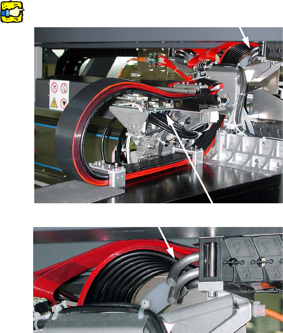
Fig. 2.8 - 6 Vacuum connection points on gantry 1+3 (initial state)
2
Fig. 2.8 - 7 Hose connection, cable and hose carrier for gantry 1+3
Assembly instructions: Vacuum pump for SIPLACE X-series
04/2009 Edition
82
Fig. 2.8 - 8 Vacuum connection points on gantry 2+4 (initial state)
Fig. 2.8 - 9 Hose connection, cable and hose carrier for gantry 2+4
2
Assembly instructions: Vacuum pump for SIPLACE X-series
04/2009 Edition
83
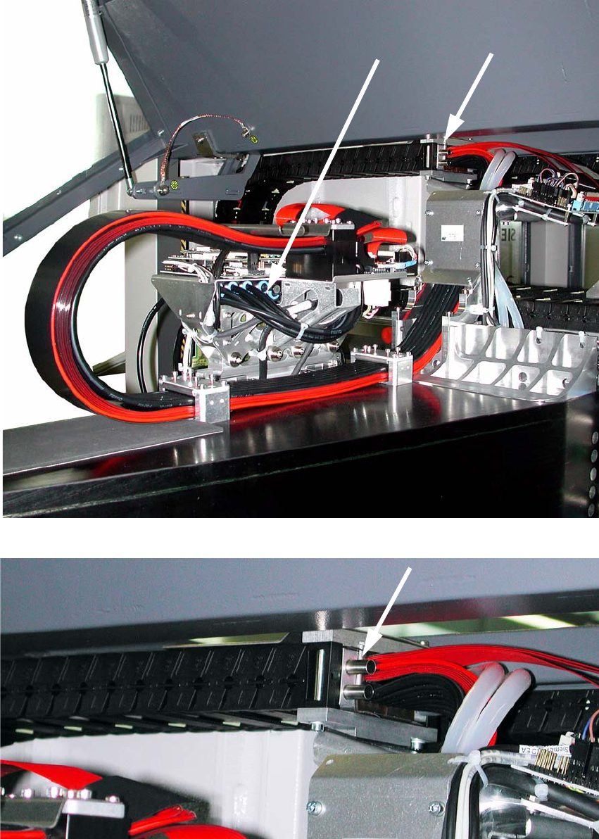
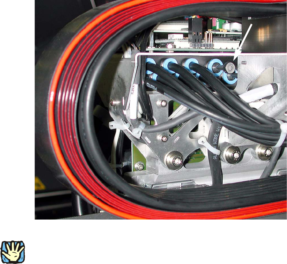
Fig. 2.8 - 10 Distributor for placement head in gantry 2+4 (initial state)
2
2
BEFORE starting any work, shut down the operating system correctly, then switch the machine
OFF at the main power switch and disconnect from the main power supply. In addition, the com-
pressed air supply must be switched off at the compressed air unit's main valve in the machine
ba
se and vented by actuating the needle valve on the compressed air unit.
2
2
2
2
2
2
2
2