00196433-02_AI_Vakuumpumpe_X-Serie_70XDE+EN.pdf - 第83页
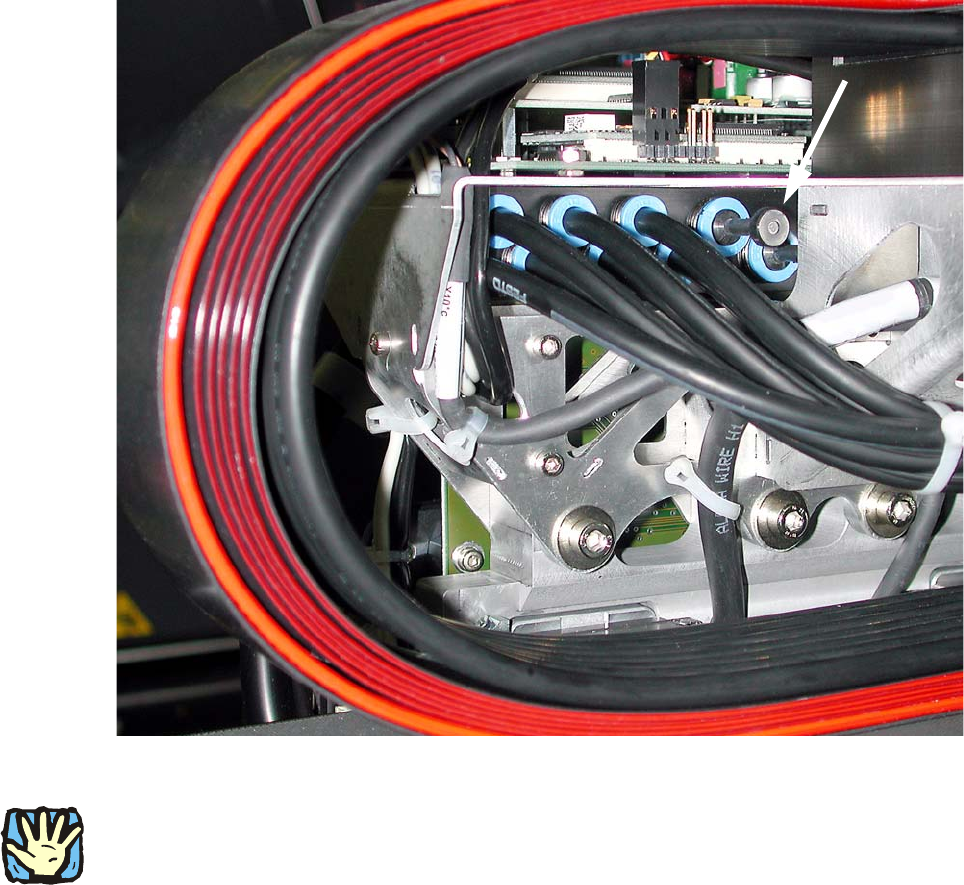
Assembly instructions: Vacuum pump for SIPLACE X-series 04/2009 Edition 83 Fig. 2.8 - 10 Distrib utor f or placement head in gantr y 2+4 (initial state) 2 2 BEFORE starting any work, shut down the oper at ing system corr…
Assembly instructions: Vacuum pump for SIPLACE X-series
04/2009 Edition
82
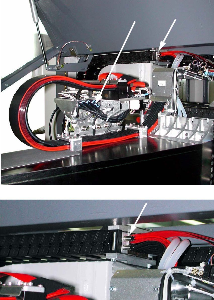
Fig. 2.8 - 8 Vacuum connection points on gantry 2+4 (initial state)
Fig. 2.8 - 9 Hose connection, cable and hose carrier for gantry 2+4
2
Assembly instructions: Vacuum pump for SIPLACE X-series
04/2009 Edition
83
Fig. 2.8 - 10 Distributor for placement head in gantry 2+4 (initial state)
2
2
BEFORE starting any work, shut down the operating system correctly, then switch the machine
OFF at the main power switch and disconnect from the main power supply. In addition, the com-
pressed air supply must be switched off at the compressed air unit's main valve in the machine
ba
se and vented by actuating the needle valve on the compressed air unit.
2
2
2
2
2
2
2
2
Assembly instructions: Vacuum pump for SIPLACE X-series
04/2009 Edition
84
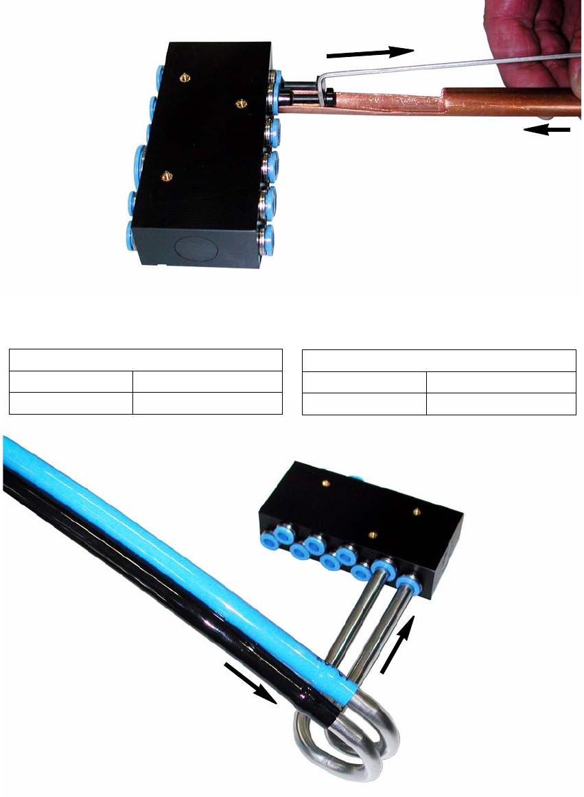
: Remove the two blanking plugs from the “distributor, placement head vacuum” on both gantries
using the release tool for Q8 (see Fig. 2.8 - 11)
Fig. 2.8 - 11 Release tool for hard-to-access connections
X2/X3/X4/X4I gantry 1/3
Tube 1
Item no.: 03075307-xx
Tube 2
Item no.: 03075308-xx
X4I gantry 2/4
Tube 1, rotated
Item no.: 03074600-xx
Tube 2, rotated
Item no.: 03074604-xx
Fig. 2.8 - 12 Distributor for placement head (removed for greater clarity)