PPS Pro version 8.2.pdf - 第112页
User Manual 4022 591 98247 108 PPS-Pro v8.2 05.07 Guidelines for using PPS-Pro 3.3.2.8 T oolbit - Alignment module compatability Due to th e variou s configur ation possibilities o f AX machines th e user has to take car…
4022 591 98247 User Manual
05.07 PPS-Pro v8.2 107
Guidelines for using PPS-Pro
setting can be done in the attributes of the machine in the ALE file, as
follows:
BadMarksRequireFiducials = “TRUE”
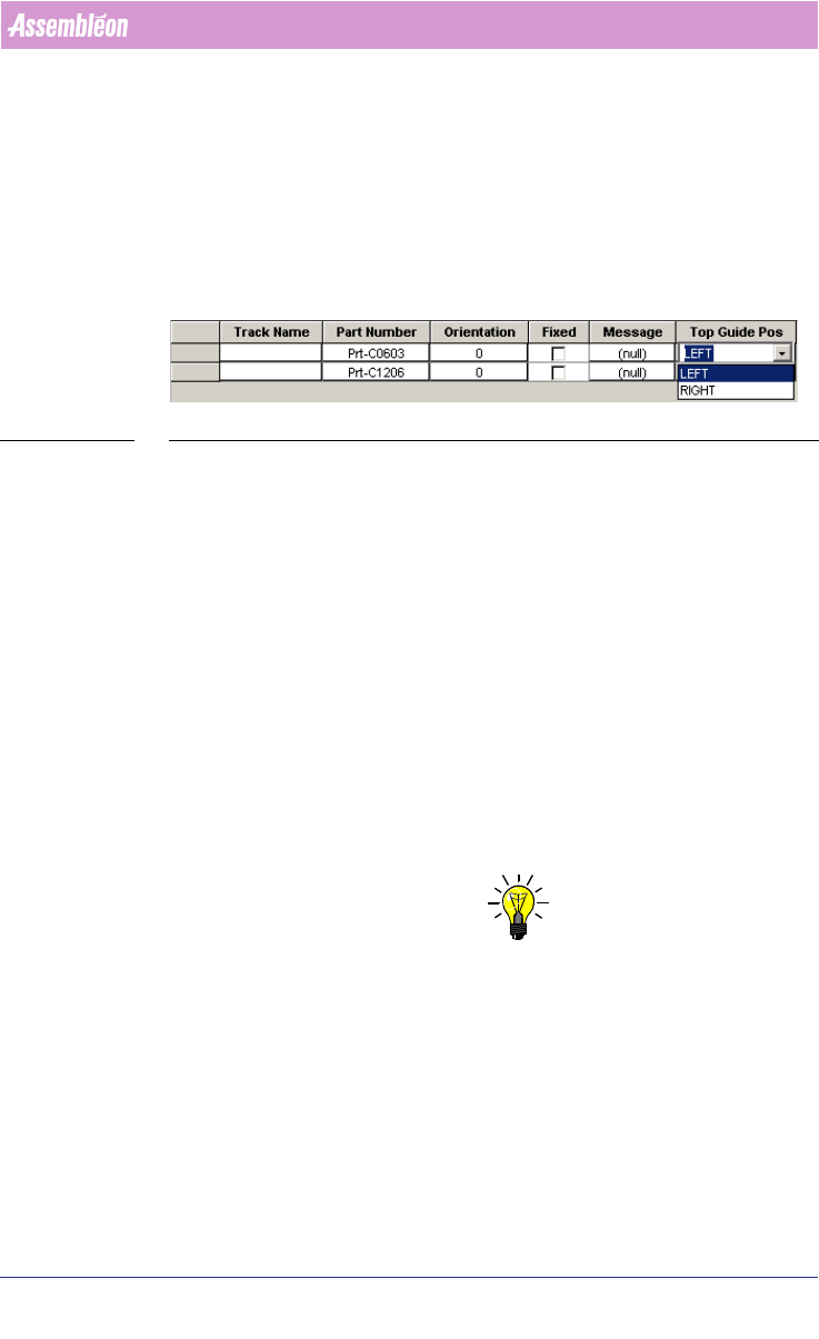
3.3.2.5 Pre-assignment of Feeder top-guide position
It is possible to assign or change the top-guide position in the CON file, two
values can be assigned ‘LEFT’ and ‘RIGHT’.
SCREEN 64 Top guide position
3.3.2.6 RTB/Line Balancer does not always assign components to
AQ machines
If the RTB or Line Balancer is used with the A-series (AQ) machines it can
happen that the RTB or Line Balancer does not assign components to AQ
machines. Via a work around (Fake nest) it is possible so the RTB/Line
Balancer will assign components. A workaround is described in the
Description ALE-file (12 nc 4022 591 98715)
3.3.2.7 Entering production fraction
If a combined product calculation is done (a calculation with multiple PCBs
selected) then it is possible to assign production fraction ‘weights’ to each PCB
that is a member of the combined product. PCB’s with a low fraction value
count less and get a lower priority, this means that the optimizer will allow a
longer production time, compared to PCB’s with a high fraction value.
NOTE: To set the production quantity/fraction the line optimizer should not be “No
optimizer” but to “Run Time Balancer”. For setting the line optimizer refer
to Installation Guide PPS-Pro v8.1 12NC 4022 591 98256. This does not
mean the RTB must be used.
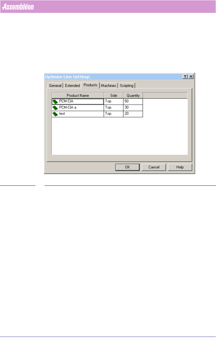
Production fraction can be set via the “Optimize Line” tab. By selecting the
“Settings”-button a new window (Optimizer Line Settings) is opened. If the
“Products”-tab is selected it is possible to enter the quantity per Product
(see
SCREEN 65 on page 108).
User Manual 4022 591 98247
108 PPS-Pro v8.2 05.07
Guidelines for using PPS-Pro
3.3.2.8 Toolbit - Alignment module compatability
Due to the various configuration possibilities of AX machines the user has to
take care that PSI toolbits can actually be used by the machine. If a package
has no toolbit that can be used in combination with any of the defined AX
alignment modules then an error message will be generated.
SCREEN 65 Setting production quantity
3.3.3 Vision methods of the AX machine
3.3.3.1 Artwork recognition on the AX machine
The AX machine has a method for board alignment called Local Mode (LAR),
which means that each placement robot (Standard & Compact) aligns its own
part of the PCB by means of measuring features on the PCB (such as pieces of
artwork). This board alignment method contributes to increased accuracy,
reduced cost of the transport system and lower production changeover times.
This strategy implies requirements on the quality of the artwork found on
PCBs.
(see 3.3.3.4 "Optimize AX machine(s) in LOCAL mode" on page 111)
Because it is not expected that all users can meet these requirements imme-
diately, the AX machine also supports the usage of traditional fiducials on
PCBs. This method is called Distributed mode (DSF). This method implies that
board alignment can be a combined effort of multiple placement robots.
(see
3.3.3.3 "Optimizing Ax machine(s) in DISTRIBUTED mode" on page 110).
4022 591 98247 User Manual
05.07 PPS-Pro v8.2 109
Guidelines for using PPS-Pro
3.3.3.2 Production modes
There are 2 methods of board alignment. These modes are configurable via the
ALE file (Refer to Descriptions ALE-file 12nc 4022 591 98715)
■ Specify operation mode (local and distributed) per panel
In combined products it is possible to specify for each PCB what its operation
mode must be for the AX ‘LOCAL’ or ‘DISTRIBUTED’.
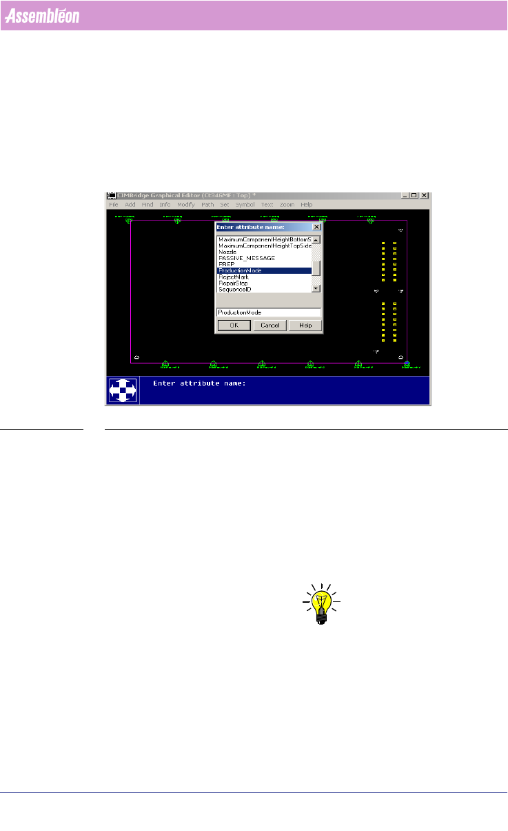
SCREEN 66 Specify operation mode per panel
The settings have to be made in the MDF-editor by selecting the Panel-outline
‘modify/attributes/add’ select ‘ProductionMode’. Here the attribute name can
be filled in ‘LOCAL’ or ‘DISTRIBUTED’. Repeat this for each board (panel).
■ Local mode
For Local mode (LAR), CAD data and Artwork info (Gerber data) may be
needed. The artwork may be needed by the Assembléon optimizer to search
for PCB board copper patterns that can be used as board alignment method
and artwork fiducial generation.
NOTE: If enough ‘standard’ fiducials (at least 2) are located for each placement
robot in each tranport index step no extra artwork extraction may be needed.
This also depends on accuracy class for the component that could be placed.
So artwork extraction can be skipped.
Each Placement robot reads it own artwork (fiducials) for board correction.
Local mode guarantees the best placement accuracy.
If not enough standard fiducials can be found by each of the placement robots
in each index step, then artwork (gerber information) can be used to find