PPS Pro version 8.2.pdf - 第129页
4022 591 98 247 User Manual 05.07 P PS-Pro v8.2 125 Guidelines for using PPS-Pro componen t databases and in the PPS compon ent database and, when n eeded, in the P art Information Mana ger . The P art Information Manage…
User Manual 4022 591 98247
124 PPS-Pro v8.2 05.07
Guidelines for using PPS-Pro
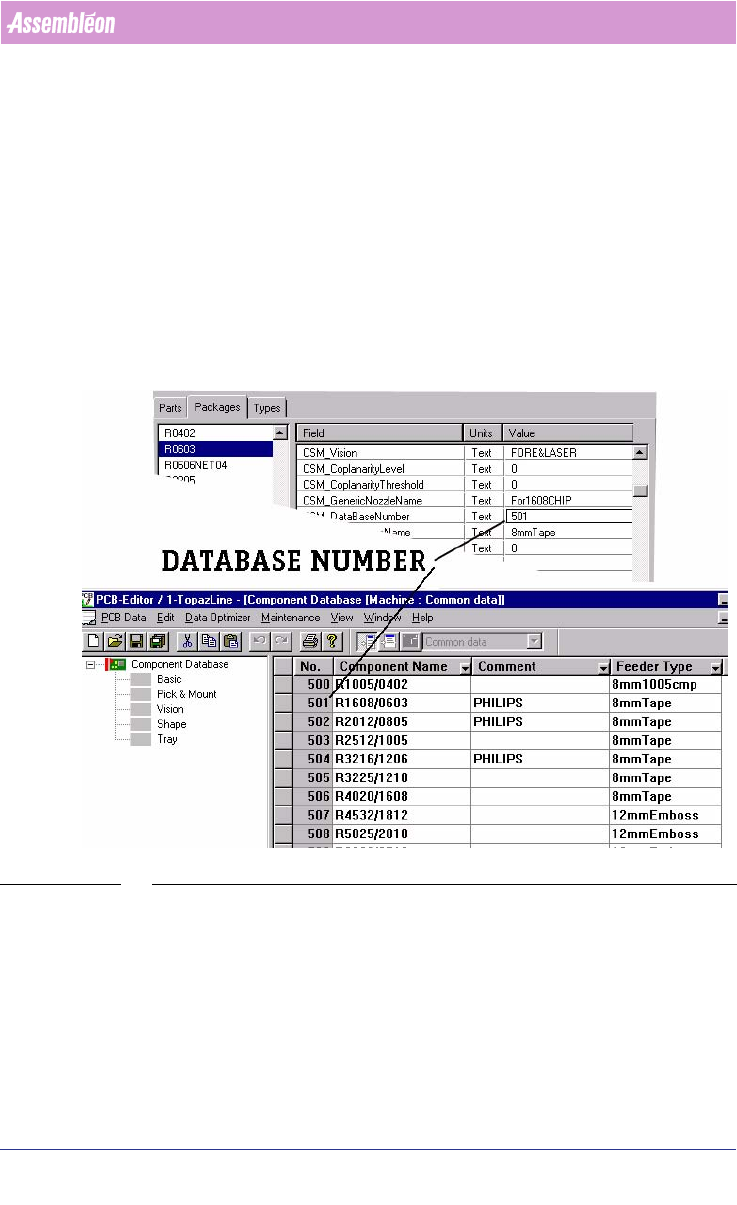
3.4.3 Component definition
Components are defined in two places, firstly by means of the Part Infor-
mation Manager in the PSI file of PPS-Pro and secondly in the GemLine
component database. On different machines the same component may require
a different alignment setting. It is advised to define each component on all
available machines with the same database number. The recognition of the
component on each machine can then be checked. Where needed the
component definition can be adapted to the specific machine situation.
When all machines have been set-up in this way and when a PCB is read in, a
“set from database” can be used. The resulting PCB should be runnable
without further modification.
SCREEN 73 Component Definition
3.4.4 Keeping PPS-Pro and Machine database the same.
In time, the databases on the machine may change. Maybe you are re-
teaching component placement information or adding new components,
which were not yet defined to the component database.
In case you change component information during production, make sure
that the component information is changed both on all your machines
4022 591 98247 User Manual
05.07 PPS-Pro v8.2 125
Guidelines for using PPS-Pro
component databases and in the PPS component database and, when needed,
in the Part Information Manager.
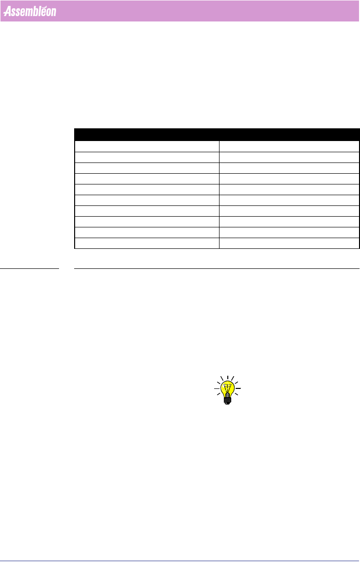
The Part Information Manager has some fields that are not used by Gemline
optimizer/generator. Instead the equivalent data in the Component Database
of Gemline PPS is used. Since the data in the Component Database comes from
the machine the data is easy to maintain.
TABLE 8 Part Information Field equivalent Component Database.
3.4.5 Tray components
GemLine machines are available in many configurations. The example machine
configurations are not always sufficient. In particular it might be necessary to
add to the ALE file information of the type of feeders available.
In the *.ale file the tray has to be defined. The component has to be defined
in the *.con file. In the *.ale file the banks have to be defined also,
depending on what kind of tray is used.
NOTE: Refer to Manual “Description ALE-file 12nc: 4022 591 98715” for Tray Defi-
nition, ATS and LCS definitions
3.4.5.1 Different CON files for Tray definitions
In Gemline PPS trays are most easily set up using the manual optimization
setting, which allows you to move the tray into the correct position using the
PPS-Pro graphical editor (MDF). After optimization the tray set-up is reported
back the Pro using the *.con file. If you want to use automatic optimization a
tray component must be fixed on the machine before optimization is started.
This is done using a *.con file as input to the optimization.
Part information field equivalent Component database field
Philips_cavity pitch Feeder Index
Philips_DMPMeth dump
Nr-refire Retry times
Fdr orient Pick Angle
Feeder type Feeder type
CSM vision Vision tab
Nozzle Availability PPS config of PCB explorer
Height, Bodywidth,Bodylenght Shape tab
Required Generic Nozzle Required Nozzle
Tray feeder type Feeder type
User Manual 4022 591 98247
126 PPS-Pro v8.2 05.07
Guidelines for using PPS-Pro
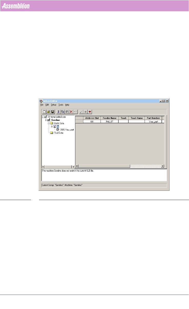
When a tray component is assigned to a GEM machine, the optimizer will
initially fail if the tray is not defined in the ALE and CON file. A CON file is
created where the specific part is defined.
An example (see SCREEN 74 "Gemline Pre-assigning a Tray" on page 126) a of
a *.CON file for a GEM machine where Tray components are defined.
To specify the fixed set-up to be used, the *.con file to be used for the
GemLine machines has to be defined in PPS-Pro.
To do this, the *.con file must be added to the optimize settings of the line.
On the optimize line tab. select settings. From the settings select machines.
In the setup file field click on the “. .. ” button. Select use existing set-up
and select the set-up file to use.
SCREEN 74 Gemline Pre-assigning a Tray
3.4.6 Multistick components
When you use multisticks, the easiest way to setup the feeder configuration is
to setup these feeders in the PCB Editor Multistick Editor. To do this run the
optimization in manual mode.
Refer to chapter 3.4.14 "Optimize Manually" and refer to the Gemline PPS User
Manual (“Optimize Manually” and “Multi Stick Feeder Assignment”.