PPS Pro version 8.2.pdf - 第138页
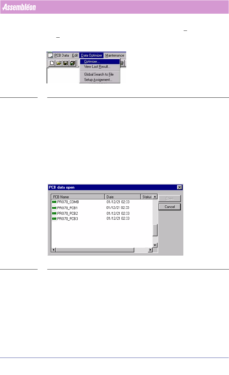
User Manual 4022 591 98247 134 PPS-Pro v8.2 05.07 Guidelines for using PPS-Pro 3. After finishing the pr e-as signed set-up, start the D ata Optimizer > O ptimizer . Sele ct the PCB PR O70_PCB1 from the P CB Setup fil…
4022 591 98247 User Manual
05.07 PPS-Pro v8.2 133
Guidelines for using PPS-Pro
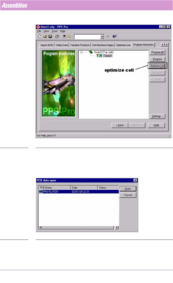
SCREEN 81 Optimize Cell
■ The CAD data is converted from PPS-Pro to GemLine optimizer/generator.
3.4.14.2 Single PCB Optimization
1. Select the PCB called PRO70_PCB1 (see SCREEN 82 on page 133).
SCREEN 82 PCB data open window
2. In the GemLine PPS PCB Editor, set-up the stick feeders and tray feeders to
the desired location.
User Manual 4022 591 98247
134 PPS-Pro v8.2 05.07
Guidelines for using PPS-Pro
3. After finishing the pre-assigned set-up, start the Data Optimizer >
Optimizer. Select the PCB PRO70_PCB1 from the PCB Setup files.
SCREEN 83 Data optimizer
4. When needed edit this PCB setup. For example to use the static database
or to use other special settings.
5. Now optimize PRO70_PCB1.
6. After optimization save the result in the proposed file PRO70_PCB1_RES
(so PPS-Pro can find it).
7. Close the result window and close the PCB editor window.
8. The data is exported back to the PPS-Pro interface.
9. The results of the optimization process are reported back to the PPS-Pro
application. PPS-Pro will now generate all required listings.
3.4.14.3 Combined PCB Optimization
SCREEN 84 Combined PCB optimization
A combined PCB is a PCB in which all components from a number of PCB’s are
combined. This method of optimization can be used to create a common
feeder setup for all PCB’s.
Practical Example:
1. Select the PCB called PRO70_COMB, when the GemLine PPS PCB editor
starts-up.
2. In Editor, set-up the stick feeders and tray feeders to the desired location
in the combined set-up.

4022 591 98247 User Manual
05.07 PPS-Pro v8.2 135
Guidelines for using PPS-Pro
3. After finishing the pre-assigned set-up, start the Data Optimizer >
Optimizer. Select the PCB PRO70_COMB from the PCB Setup files.
4. When needed edit this PCB setup. For example to use the static database
or use other special settings.
5. Now optimize PRO70_COMB.
6. After optimization save the result in the proposed file PRO70_COMB_RES
(so PPS-Pro can find it).
7. Select all the PCB’s to be optimized (for e.g. PRO70_PCB1, PRO70_PCB2
etc.,) and start optimization for these PCB’s.
8. After optimization finishes save all the results of PCBs with the proposed
PCB names, PRO70_PCB1_RES, PRO70_PCB2_RES etc.
9. Close the result window and close the PCB editor window.
10. The results of the optimization process are reported back to the PPS-Pro
application. PPS-Pro will now generate all required listings.
3.4.14.4 Feeder position - TopazXi
■ Description: The feeder bar for a TopazXi machine is defined as containing
40 positions (1-40). This information will be used by the run time
balancer during the allocation of feeders to feeder bar slots. The run time
balancer could assume that it is possible to allocate a 44 mm feeder to
positions 19 to 21. In reality the TopazXi has two feeder bars with 20
positions each, with a camera in between. It could be a problem if too
many large feeders are assigned to the TopazXi machine. The calculation
that takes place after line balancing will not be able to find a solution if it
gets too many parts
■ Advice: Re-allocate some components to other machines.
3.5 Set feeder inventory
To set limited resources for feeders on machines the inventory values in the
ALE file can be changed. Refer to manual Description ALE-file 12nc 4022 591
98715.
NOTE: Setting limited resources for feeders affects the optimizer result.
If the inventory is set to a limited value the optimizer is restricted to assign a
maximum number of the specified feeder type. This may affect the quality
(output) of the calculated results.
Setting limitless resources for feeders can be done in two ways.
1. Set the value in the Inventory field to ‘1000’.
2. Omit the Inventory field for feeders entirely.