PPS Pro version 8.2.pdf - 第45页
4022 591 98 247 User Manual 05.07 PPS-Pro v8.2 41 PPS-Pro GUI Each boar d has it s own boar d-id. This is a nu mber that is st ored with ea ch object that bel ong s to the boar d. The boar d-id is sh own when on e or mor…
User Manual 4022 591 98247
40 PPS-Pro v8.2 05.07
PPS-Pro GUI
2.12.4 Copy a BOM format
To copy an existing format just select a format and press the Copy icon (see
SCREEN 23 on page 32) of the ‘BOM-Formats Explorer’. The name of the copied
file is ‘Copy of <initial format name>’.
2.13 Graphical/MDF editor
NOTE: Basic help on functionality can be found via the help in the Cimbridge
Graphical Editor (MDF editor). For details on help, go to the
Help menu and
click Help Contents then click a menu item.
NOTE: General information in the Graphical/MDF editor on the opened Product can
be done via Menu:
Info > Info Drawing
2.13.1 Entering board thickness
Board thickness can be set via the Set > Board Thickness command. This will
define the board thickness of the PCB in the MDF file. Setting correct infor
-
mation about the thickness of the PCB is neccessary before a calculation for
an A-Series line can be started.
2.13.2 Panel, board, SNR symbol and board id
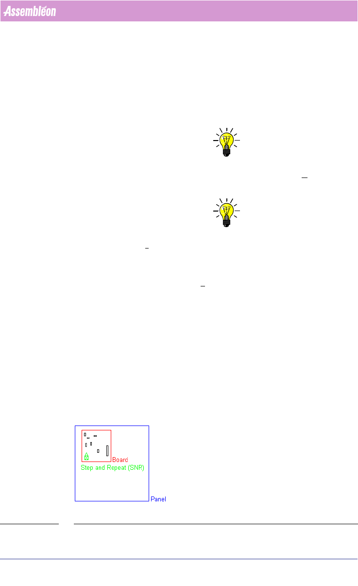
A PCB is referred to as a panel in an mdf file. A panel may consist of one or
more boards (circuits)
(see FIGURE 2 on page 40).
In an mdf file, each board is represented by its own SNR symbol. The SNR
symbol can be considered a placeholder for the components that belong to the
board the SNR symbol represents.
FIGURE 2 Panel
4022 591 98247 User Manual
05.07 PPS-Pro v8.2 41
PPS-Pro GUI
Each board has its own board-id. This is a number that is stored with each
object that belongs to the board. The board-id is shown when one or more
parts have been selected in mdf edit and when the F3 (info parts) button is
pressed. The board-id is the number shown between braces after ‘Board’.
When a panel consists of more identical copies of one board the user has to
make copies of the step-and-repeat symbol. This can be done in the ‘MDF
editor’ or in the Panelize Products tab in the PPS-Pro graphical user interface.
When a copy has been made of a step-and-repeat symbol, the accompanying
parts of the circuit are not shown by default. It is possible to get a
(temporary) display by typing the command ‘snr’ in the MDF editor command
line.
It is possible to copy the images into the panel. If you choose to do so, make
sure you assign new board ids.
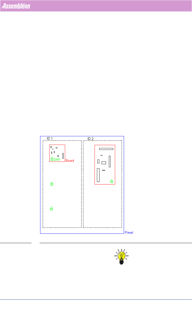
It is also possible to have a situation where different boards are present on
one panel. In this case each original board will have its own board-id. When
identical copies of an original board are made the step-and-repeat symbols
inherit the respective board ids. Make sure that the board id of every SNR
symbol refers to the correct original board.
FIGURE 3 Board ID and Step-and-Repeat symbol
NOTE: All objects within a separate dashed line have the same Board ID. Here ID1
and ID2 are separate. Each SNR stands for all parts that belong to the corre
-
sponding board (see FIGURE 3 on page 41).
User Manual 4022 591 98247
42 PPS-Pro v8.2 05.07
PPS-Pro GUI
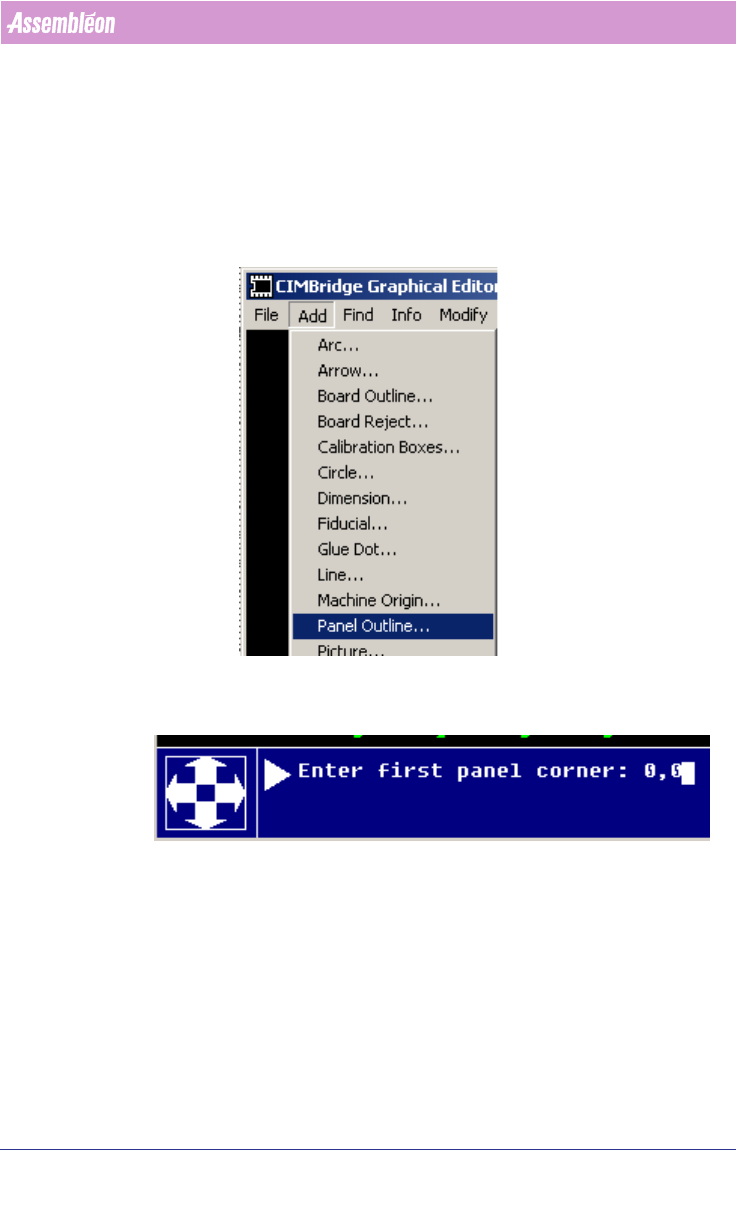
2.13.3 Entering panel outline
When the smartcad importer has been used the panel outline has to be added
manually with the MDF editor, this can be done as follows:
1. Start MDF edit on the imported PCB (Select view button)
2. Select Add > Panel outline
3. Enter the X, Y coordinates of the PCB below, on this screen:
4. After the first corner has been entered, the dialog continues and asks for
the second corner. Enter these coordinates (X,Y) and enter. Now the panel
outline will be shown.
Note that for adding board (=circuit) outlines, first draw the circuit contour
and make this one symbol with Symbol > Build symbol, then use Add >
Board outline to convert this graphic into the requested contour outline.
Revert to MDF help for further details.