PPS Pro version 8.2.pdf - 第97页
4022 591 98 247 User Manual 05.07 PPS-Pro v8.2 93 Guidelines for using PPS-Pro weigh t fa ctor ea ch PCB has, f or example one coul d enter the nu mber of PCBs that have to be pr oduced. The feature w orks f or both A-Se…

User Manual 4022 591 98247
92 PPS-Pro v8.2 05.07
Guidelines for using PPS-Pro
The following actions must be done to obtain a combined product calculation:
All products (mdf-files) which must be combined have to be part of the same
project. Two cases can be distinguished:
1. The PCBs have identical dimensions and they are derived from the same
original CAD design. The PCBs are considered members of the same family.
The user has to take care that all parts that belong to the same circuit pattern
must have the same board-id in every MDF file.
The PCBs are unequal.
The user has to take care that all board-ids are unique.
Setting the board id can be done as follows:
Edit the MDF file using the MDF editor. Select all parts that belong to a
particular circuit, choose the Set > Board ID... menu item and enter a
positive integer (1, 2, 3 etc.)
(see 2.13 "Graphical/MDF editor" on page 40).
In the Program Machines tab of the main application all PCBs that have to be
combined need to be enabled explicitly. If a PCB is not enabled it will not be
part of the results of the combined product calculation. The entire calculation
needs to be done again.
(see 2.25 "Program Machines Tab" on page 61)
When the requested PCBs have been enabled the Program All button (see
SCREEN 42 "Program All" on page 65) can be used to start the preparation
phase (phase 1) of the calculation, which collects all data needed by the
optimizer.
After a successful completion of ‘Program All’, the Optimize Cell button will
be enabled. Clicking this button will start the actual optimization for the
combined product. When the combined product calculation has completed
successfully all action specifications are accessible from this screen. Note that
with the new ‘Optimizer Monitor’ a running calculation can be analysed and
stopped at any time of the optimization process.
3.1.10 Maximum runtime settings in Combined & Family
product calculations
If in case of a combined product or family product calculation the setting:
‘Max. Run Time’ and ‘Desired Cycle Time’
(see SCREEN 40 "Philips Optimizer
Machine-Specific Controls Powerline and A-Series" on page 63) of the selected
product in the ‘Select Product’ tab is used. The product shown at the bottom
of the “Program Machine” tab is the first selected.
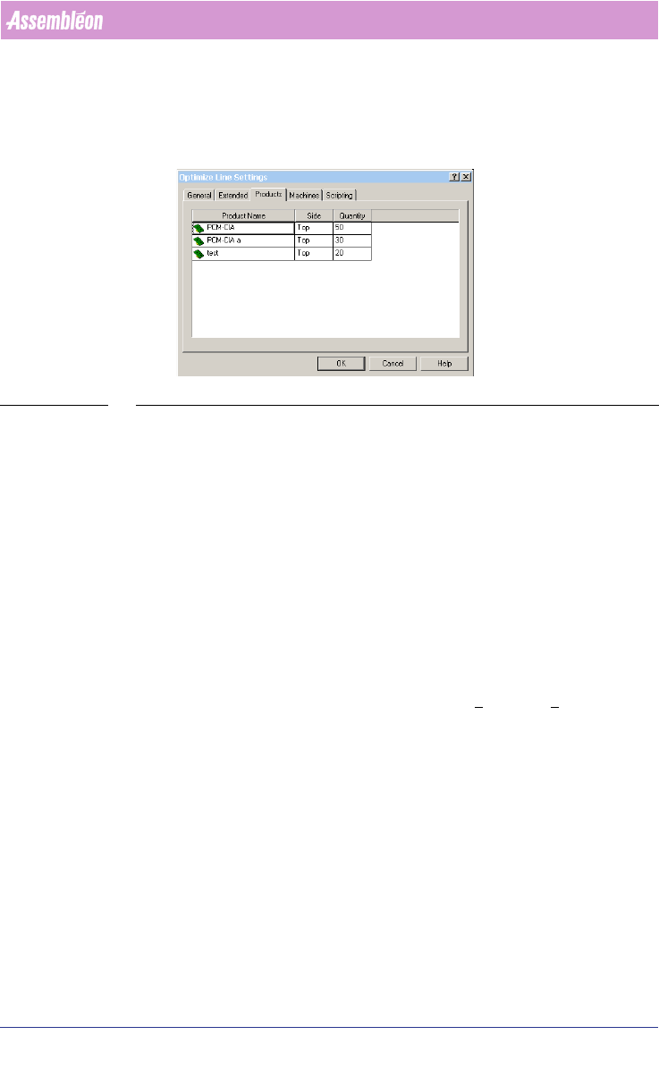
3.1.11 Setting Production Quantity for Family and Combined
Production.
It is possible to set the production quantity per member of a family- or
combined product. The optimizer will optimize so the PCB(s) with the largest
production fraction has the best output. The numbers represent the relative
4022 591 98247 User Manual
05.07 PPS-Pro v8.2 93
Guidelines for using PPS-Pro
weight factor each PCB has, for example one could enter the number of PCBs
that have to be produced. The feature works for both A-Series and FCM/ACM
optimizers.
SCREEN 59 Setting Production Quantity
3.2 PowerLine Guidelines for PPS-Pro
For information on ALE and PSI about the PowerLine use the manuals
Description ALE-file (12nc 4022 591 98715) and the Description PSI-file
(12nc 4022 591 98815)
3.2.1 Define artwork reference for fiducials and badmarks
Fiducials and badmark settings for Powerline must be set in the ALE file (Refer
to Description ALE-file 12NC 4022 591 98715)
3.2.2 FFA support (FCM)
Fixed Fiducial Alignment (FFA) is supported. An environment variable must be
set. This can be done in ‘Windows™’ in the Start >
Settings > Control Panel >
System and then the Environment tab. The variable to set is:
‘FCM_FFA_CNF’
This value indicates the index step in which the FFA action takes place.
Known restrictions on this implementation of FFA:
■ This method does not work in combined FFA & BVM lines.
■ FFA in index 0 is not supported.
3.2.3 Pre-pick on ACM
The environment variable ‘ACM_PREPICK’, which is needed for obtaining ACM
prepick, default is set to ‘YES’. It is possible to set this variable to ‘NO’. This

User Manual 4022 591 98247
94 PPS-Pro v8.2 05.07
Guidelines for using PPS-Pro
can be done in ‘Windows™’ in the Start > Settings > Control Panel > System
and then the Environment tab.
When this value is set to ‘YES’, prepick actions will be generated.
Examples:
First part of Actions when ‘ACM_PREPICK’ is set to ‘YES’ or when it is omitted:
[ACTION]
PICK HD2 1 2215_ FB1 241
PICK HD1 1 2013_ FB1 241
ALIGN HD1 1 2013_ CA1
ALIGN HD2 1 2215_ CA2
FIDUCIAL FA1 1 2
MOUNT HD1 1 2013_
MOUNT HD2 1 2215_
First part of Actions when ‘ACM_PREPICK’ is set to ‘NO’:
[ACTION]
FIDUCIAL FA1 1 2
PICK HD2 1 2215_ FB1 241
PICK HD1 1 2013_ FB1 241
ALIGN HD1 1 2013_ CA1
ALIGN HD2 1 2215_ CA2
MOUNT HD1 1 2013_
MOUNT HD2 1 2215_
NOTE: Combination of pre-pick and placelast is not supported.
3.2.4 Placement of RNET and CNET components on FCM
When the FCM is equipped with the ‘Compact Laser Module II’ (PA 1150/04)
which is also referred to as ‘CLM II’ it is possible to select ‘RNET’ mode
[intended for all ‘RNET’ (Resistor Network) as well as ‘CNET’ (Capacitor
Network) packages]. This is done by means of connecting a special cable. In
‘RNET’ mode the module executes a different vision algorithm for some
packages.
In ‘PPS-Pro’ it is possible to force the assignment of ‘RNET’ parts to ‘RNET’
configured modules. This effect is obtained by assigning to the ‘RNET’ package
a newly introduced nozzle, this way all parts that do not contain this nozzle
cannot be assigned to the placement module. For this assignment two new
artificial nozzle definitions have been added to the allowed list of nozzles that
can be assigned to a package, these are 4720R and 4730R.
The user who wants to place ‘RNET’ and ‘CNET’ packages can assign the
respective 4720R or 4730R nozzle in the alternate nozzle fields (*_2 fields) of