00195044-22_UM_VisionTeachStation_5.x.x_DE_EN.pdf - 第119页
Vision Teach Station 5.x.x User Manual 4 Setting up the vision teach station 05/2019 Edition 4.3 Camera and CAN bus connections on the PC 27 4.3 Camera and CAN bus connections on the PC 4 Fig. 4.3 - 2 Connectors and LE D…
4 Setting up the vision teach station Vision Teach Station 5.x.x User Manual
4.2 Connections and LED displays on the base module 05/2019 Edition
26
4.2 Connections and LED displays on the base module
4
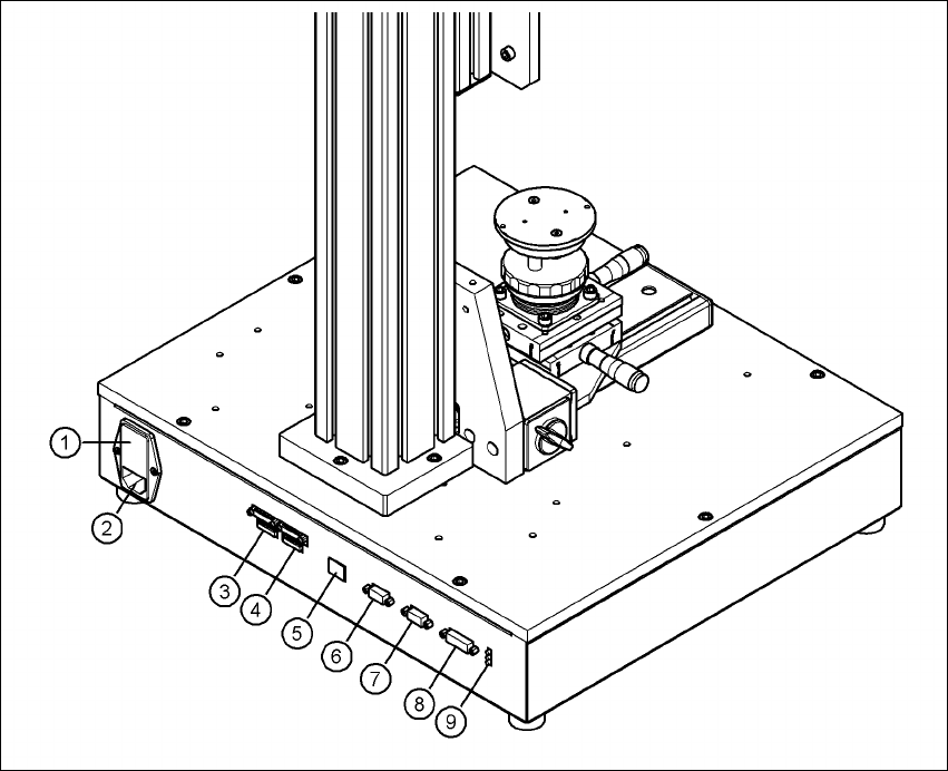
Fig. 4.2 - 1 Connectors and LED displays on the base module
(1) Power switch and fuse holder for the 2.5 A fuse
(2) Power socket (110 VAC to 240 VAC)
(3) Connection for cable, head camera 1 (03040353-W1: 26-pin, 03040353-W2: 12-pin)
(4) Connection for cable, head camera 2 (03040353-W1: 26-pin, 03040353-W2: 12-pin)
(5) Connection for camera bus cable to the PC (03040359-xx) (only if head camera is installed)
(6) Connection for CAN bus cable to the PC (03040362-xx)
(7) Connection for CAN bus cable to the stationary camera (03040355-W2)
(8) Connection for the power supply cable for the stationary camera (03040355-W1)
(9) LED displays for supply voltages, from top to bottom:
+ 24 VDC- (red)
+ 15 VDC- (yellow)
+ 42 VDC- (green)
Vision Teach Station 5.x.x User Manual 4 Setting up the vision teach station
05/2019 Edition 4.3 Camera and CAN bus connections on the PC
27
4.3 Camera and CAN bus connections on the PC
4
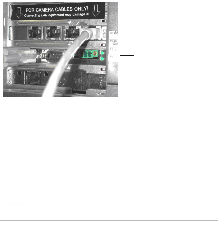
Fig. 4.3 - 2 Connectors and LED displays on the base module
(1) Camera bus interface with 4 connections
(2) CAN bus interface with 2 connectors
(3) SIPLACE LAN interface
4.4 Connecting the CAN bus between base module and PC
Connect the 3 m CAN bus cable (item no. 003040362-xx) to the connector on the base module
(item 6 in Fig. 4.2 - 1
, page 26).
Tighten the two screws to secure the connector.
Plug the CAN bus cable into one of the two sockets on the CAN bus interface (item 2 in Fig.
4.3 - 2
).
Tighten the two screws to secure the connector.
NOTE 4
The procedure for connecting the camera bus cable is described in the sections for the different
cameras.
(1)
4
(2)
4
(3)
4 Setting up the vision teach station Vision Teach Station 5.x.x User Manual
4.4 Connecting the CAN bus between base module and PC 05/2019 Edition
28