00195044-22_UM_VisionTeachStation_5.x.x_DE_EN.pdf - 第180页
12 Coordinate systems of the comp onent cameras Vision Teach Station 5.x.x User Manual 05/2019 Edition 88 12 Fig. 12.0 - 3 Alignment of the components in the preferr ed 0° position - SST 28/29/30, SST 33/36/25 Y X X Y + …
Vision Teach Station 5.x.x User Manual 12 Coordinate systems of the component cameras
05/2019 Edition
87
12 Coordinate systems of the component cameras
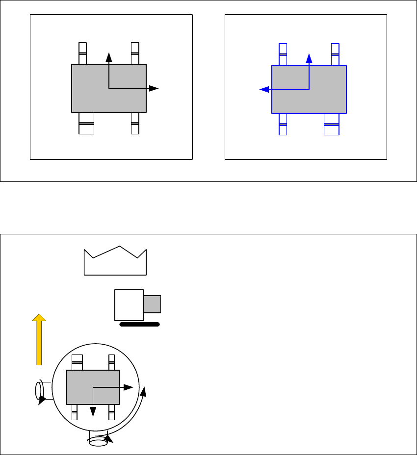
Representation of the preferred 0° position on the SIPLACE Pro computer and on the vision
teach station 12
The following illustrations show how the package form is represented in the preferred 0° position
on the SIPLACE Pro computer or on the SIPLACE vision teach station.
12
Fig. 12.0 - 1 Representation of the preferred 0° position on the SIPLACE Pro computer and on the vision teach station
Alignment of the components in the preferred 0° position 12
12
Fig. 12.0 - 2 Alignment of the components in the preferred 0° position - SST 23
X
Y
2
X
Y
SIPLACE Pro computer
SIPLACE Vision Teach Station
+
Y
X
X
Y
SST23
0° component position
on the component camera
of the C&P20 head
12 Coordinate systems of the component cameras Vision Teach Station 5.x.x User Manual
05/2019 Edition
88
12
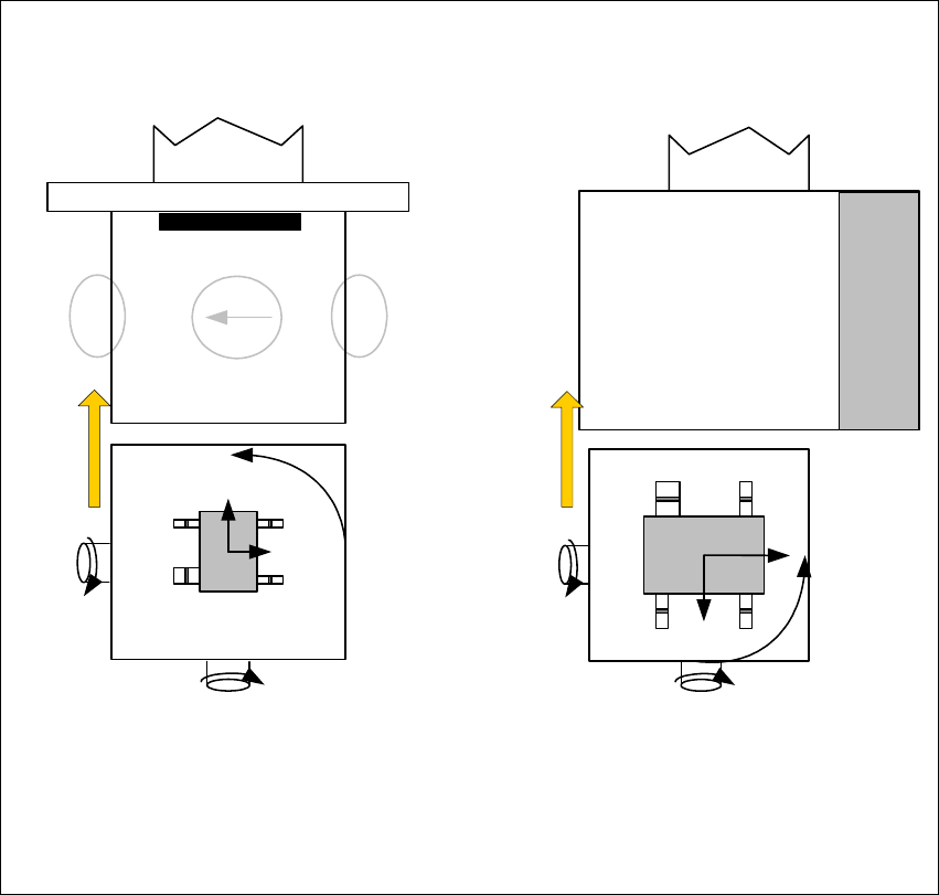
Fig. 12.0 - 3 Alignment of the components in the preferred 0° position - SST 28/29/30, SST 33/36/25
Y
X
X
Y
+
X
Y
+
Y
X
0° component position on
C&P6/12 cameras -
plan view
Direction of rotation of the
star
0° component position
on stationary cameras -
plan view
The gray shading on the camera marks the
illumination part of the 0° plane
SST 28 / SST 29 / SST 30 SST 33 / SST 36 / SST 25

Vision Teach Station 5.x.x User Manual 13 Focus distances of the component cameras
05/2019 Edition
89
13 Focus distances of the component cameras
The focus distances between the individual component cameras and the component are listed in
the following table.
13
Tab. 13.0 - 1 Focus distances of the component cameras
Component camera
type
Focus distance Notes
23/41 1 mm
The distance is measured between the inner edge of the light
fitting and the body of the component.
25 2 mm
–
28/29/30 3 mm
–
33/36 5 mm
–