00195044-22_UM_VisionTeachStation_5.x.x_DE_EN.pdf - 第124页
5 Installing the cameras Vision Teach Station 5.x.x User Manual 5.1 Installing stationary cameras, type 25, 33 and 36 05/2 019 Edition 32 Fig. 5.1 - 4 DIP switch settings on the stationary cameras (version with 6 switche…
Vision Teach Station 5.x.x User Manual 5 Installing the cameras
05/2019 Edition 5.1 Installing stationary cameras, type 25, 33 and 36
31
5
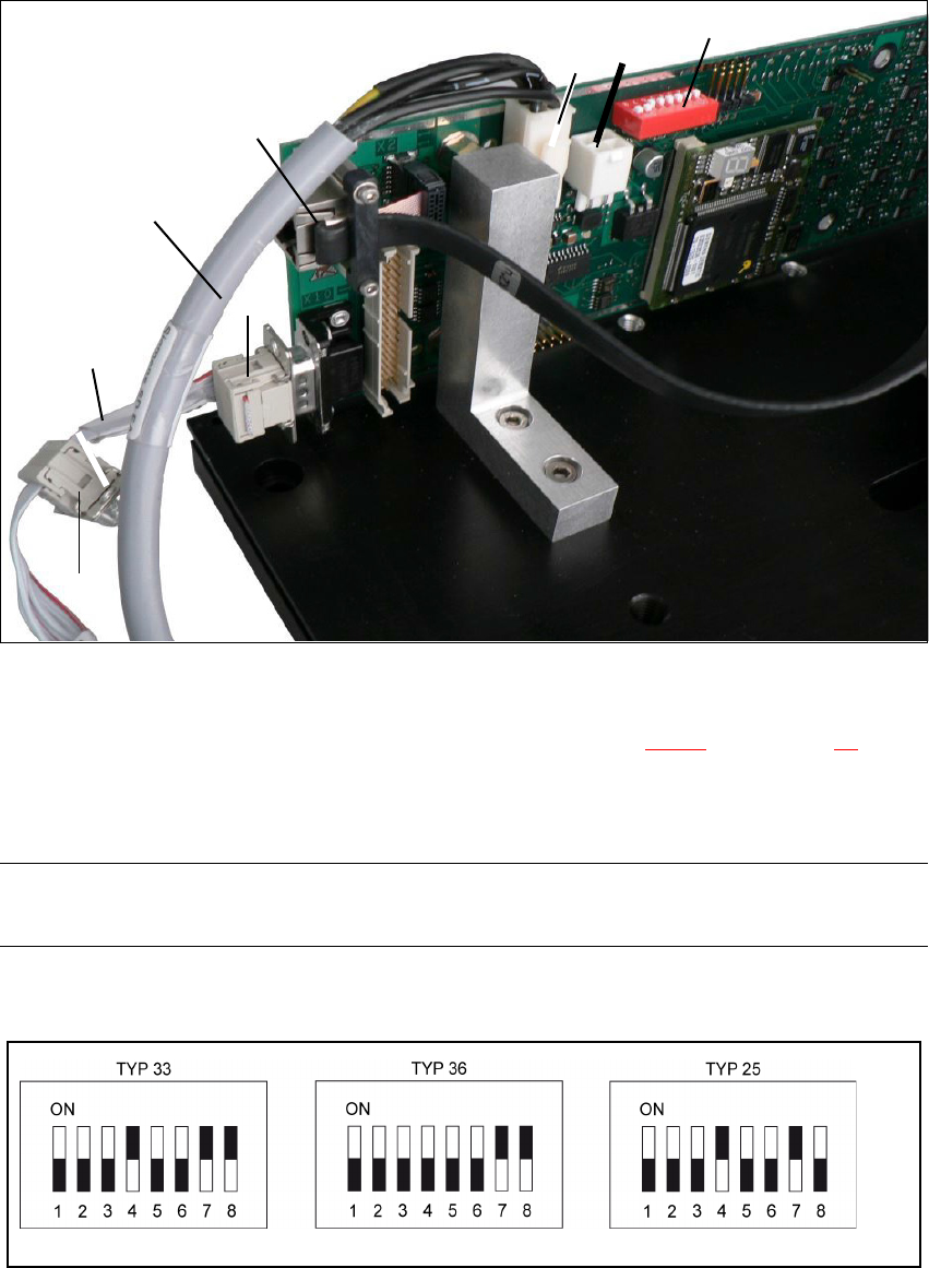
Fig. 5.1 - 2 Connecting cable set 03040355-xx
(1) DIP switches for camera type and location address
(2) Camera connector for camera cable direct to the PC (see Fig. 4.3 - 2
, no. 1, page 27)
X4, X5 power supply connection, connected in parallel
X10 CAN bus connection
NOTE 5
Fit the camera to the base module before you connect the camera bus cable.
Check the DIP switch settings on the cameras.
Fig. 5.1 - 3 DIP switch settings on the stationary cameras for the vision teach station (version with 8 switches)
03040355-W2
X12
03040355-W1
(1)
(2)
X4
X10
X5
5 Installing the cameras Vision Teach Station 5.x.x User Manual
5.1 Installing stationary cameras, type 25, 33 and 36 05/2019 Edition
32
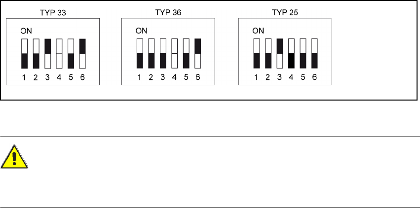
Fig. 5.1 - 4 DIP switch settings on the stationary cameras (version with 6 switches)
CAUTION 5
In the version with 6 switches, switch no. 4 must NOT be changed, as this might cause malfunc-
tion of the LED self test.
5
Vision Teach Station 5.x.x User Manual 5 Installing the cameras
05/2019 Edition 5.1 Installing stationary cameras, type 25, 33 and 36
33
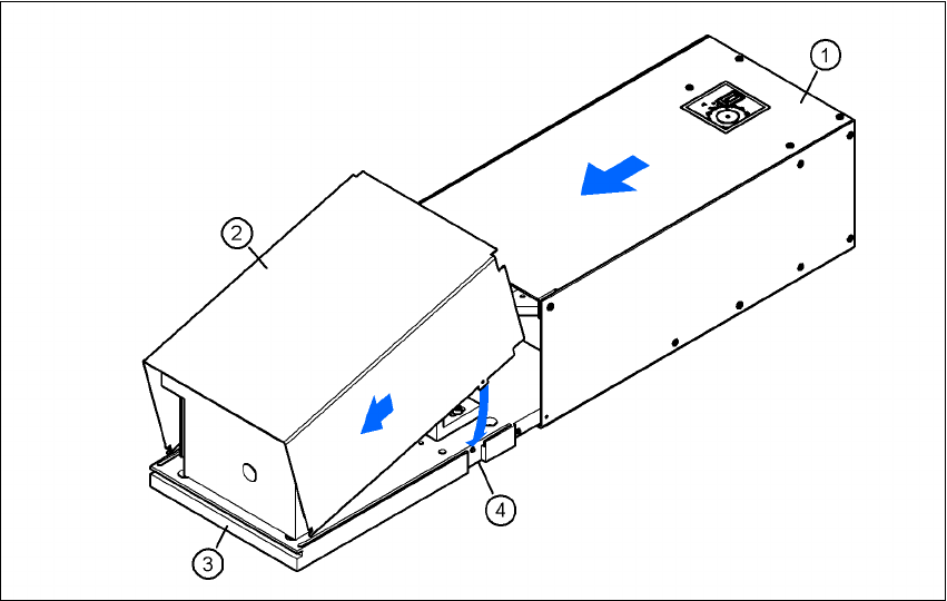
5.1.1.3 Assembling the camera
Slide the cover (item 2) nose-first into the base plate (item 3).
Swivel the cover down until it engages on the ball catch (item 4) in the base plate (item 3).
Slide the illumination head (item 1) back until it engages.
5
Fig. 5.1 - 5 Assembling the camera