00195044-22_UM_VisionTeachStation_5.x.x_DE_EN.pdf - 第128页
5 Installing the cameras Vision Teach Station 5.x.x User Manual 5.1 Installing stationary cameras, type 25, 33 and 36 05/2 019 Edition 36 5 Fig. 5.1 - 7 Fixing camera type 33 to the pillar

Vision Teach Station 5.x.x User Manual 5 Installing the cameras
05/2019 Edition 5.1 Installing stationary cameras, type 25, 33 and 36
35
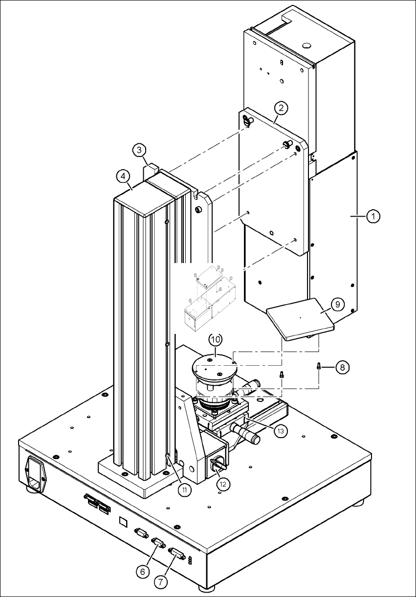
5.1.2.3 Fixing camera types 33, 36 and 25 to the pillar
Use the two special screws to fix the camera (item 1 in Fig. 5.1 - 7, page 36) in the cut-outs in
the mounting plate (item 3 in Fig. 5.1 - 7
, page 36).
Fix the mount (item 2 in Fig. 5.1 - 7, page 36) to the mounting plate (item 3 in Fig. 5.1 - 7, page
36
) using the 4 hexagon socket head screws M6 x 20 (item 5 in Fig. 5.1 - 7, page 36).
WARNING 5
Make sure that the camera is attached firmly to the mounting plate (item 3 in Fig. 5.1 - 7
, page
36
). For safety reasons, it must be screwed to the mounting plate with the 4 hexagon socket
head screws M6 x 20.
Release the lock on the positioning unit (item 13 in Fig. 5.1 - 7, page 36 by turning the knob
(item 12 in Fig. 5.1 - 7
, page 36) on the magnetic switch towards the pillar.
Push the positioning unit (item 13 in Fig. 5.1 - 7, page 36) out of the camera range.
Fix the component support (item 9 in Fig. 5.1 - 7, page 36) using the two hexagon socket head
screws M3 x 8 (item 8 in Fig. 5.1 - 7
, page 36) to the holder (item 10 in Fig. 5.1 - 7, page 36).
After fitting the component support, lock the positioning unit once more.
5 Installing the cameras Vision Teach Station 5.x.x User Manual
5.1 Installing stationary cameras, type 25, 33 and 36 05/2019 Edition
36
5
Fig. 5.1 - 7 Fixing camera type 33 to the pillar
Vision Teach Station 5.x.x User Manual 5 Installing the cameras
05/2019 Edition 5.1 Installing stationary cameras, type 25, 33 and 36
37
Key to figure 5.1 - 7, page 36
(1) Camera, type 33, 36 or 25
(2) Mount, type 33/36 or 25
(3) Mounting plate
(4) Pillar
(5) Hexagon socket head screw M6 x 20, 4x
(6) X2: CAN bus connection for stationary camera
(7) X1: Power supply connection for stationary camera
(8) Hexagon socket head screw M3 x 8, 2x
(9) Component support, camera type 25/33/36, complete
(10) Holder for component support
(11) Cable ties, 3x
(12) Magnetic switch
(13) Positioning unit
5
5.1.3 Connecting camera type 33, 36 or 25
CAUTION 5
Make sure that the base module and PC are switched off before connecting any cables.
Connect connector X2 on cable 03040355-W2 to socket X2 (item 6 in Fig. 5.1 - 7, page 36) on
the base module.
Connect connector X1 on cable 03040355-W1 to socket X1 (item 7 in Fig. 5.1 - 7, page 36) on
the base module.
Plug the camera bus cable 03040359-xx into the RJ45 socket on the camera (item 2 in Fig. 5.1
- 2, page 31).
Connect the other end of the camera bus cable to the camera bus interface on the PC (item 1
in Fig. 4.3 - 2
, page 27).
Fix the cables 03040355, W1 + W2 and 03040359-xx to the pillar using 3 cable ties
(item 11 and item 4 in Fig. 5.1 - 7
, page 36).
Make sure that the bending radii of the cables are large enough and that there is little tension
so that the cables are not damaged.