00195044-22_UM_VisionTeachStation_5.x.x_DE_EN.pdf - 第143页
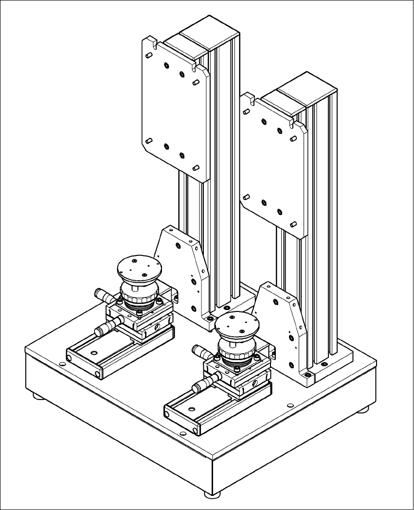
Vision Teach Station 5.x.x User Manual 6 2nd camera option 05/2019 Edition 6.1 Vision teach station upgrade 51 6 Fig. 6.1 - 1 Assembly position for the t wo pillars

6 2nd camera option Vision Teach Station 5.x.x User Manual
6.1 Vision teach station upgrade 05/2019 Edition
50
6.1.4 Connecting two stationary cameras
If there is also a stationary camera (SST33, 36 or 25) used on the second pillar, the main power
supply and the CAN bus are plugged directly into the camera on the first pillar, rather than into the
base module. You will need cable kit 03040352 to do this.
First plug this cable kit into the second, additional camera following the instructions in section
5.1.1
, page 30.
Fit the camera onto the second pillar following the instructions in section 5.1.2, page 34.
Then connect the cable 03040352-W1 to connector X5 on the camera on pillar 1. Connector
X5 is difficult to access while the housing cover is fitted.
To access the connector, you should ideally put the vision teach station on the floor and remove
the dust cover (foam rubber) so that you can see in clearly from above. Connector X5 is be-
neath connector X4, or, as shown in Fig. 5.1 - 2
, page 31, to the right of X4. The connectors
X4 and X5 are interchangable.
Connect cable 03040352-W2 to connector X12 from cable kit 03040355 (see Fig. 5.1 - 2, page
31
, bottom left).
Vision Teach Station 5.x.x User Manual 6 2nd camera option
05/2019 Edition 6.1 Vision teach station upgrade
51
6
Fig. 6.1 - 1 Assembly position for the two pillars
6 2nd camera option Vision Teach Station 5.x.x User Manual
6.1 Vision teach station upgrade 05/2019 Edition
52