Operating Manual SIPLACE Multi-Docking Station.pdf - 第20页
3 Product Description SIPLACE Multi-Docking-St ation 3.1 Functional Description Operating Manual 16 The major functions of the Multi-Doc king St ation are: – Su pplying the compo nent cart and the X feeder modules with…

15
SIPLACE Multi-Docking-Station 3 Product Description
Operating Manual 3.1 Functional Description
3 Product Description
Part No. 00176145-01 SIPLACE Multi-Docking Station
3.1 Functional Description
General
The SIPLACE Multi-Docking Station is an
additional component to the pre-setup station. It is the
link between the pre-setup station and the component cart of the SIPLACE X and SX series. The
docking station allows the external setup of component carts with feeder modules, function tests
and setup checks for the sizes COT 30, 40 and 60.
Fig. 3 - 1 SIPLACE Multi-Docking Station
(1) SIPLACE Multi-Docking Station (6) Control buttons
(2) Component cart docking device (7) EDIF (power and data interface)
(3) Skid strips for guiding and docking the
compon
ent table
(8) Adjustable feet for height adjustment and
fastening to the ground
(4) Pneumatic cylinder for locking the
compon
ent cart
(9) Detent pin for transport height adjustment
(5) Sensor for component cart detection (10)Support for adapter COT 30 / 40.
1
5
3
2
4
7
8
6
3
4
9
10
3 Product Description SIPLACE Multi-Docking-Station
3.1 Functional Description Operating Manual
16
The major functions of the Multi-Docking Station are:
– Supplying the component cart and the X feeder modules with power
– Providing an infrastructure for the communication
between the PC of the pre-setup station and
the feeder modules
The user can use the Multi-Docking St
ation to conduct function tests on the X feeder modules and
to check the setups outside the production environment. For this purpose, two rows each having
four Multi-Docking Stations are connected via the CAN bus of the pre-setup PC. Each docking
station has its own power and compressed-air connections.
The docking station’s component cart docking d
evice can be adjusted to the desired PCB
transport height. The component cart is pushed into the Multi-Docking Station for the pre-setup.
The component cart slides by roller bearings mounted to its sides on the rails of the component
cart docking device to the power and data interface connector (EDIF). The EDIF in the component
cart docking device is properly positioned to the component table with the EDIF of the feeder
modules.
Component carts of sizes COT 30, 40 and 60 can be used. Optional accessories allow quick and
easy conver
sion.
The standard type of the Multi-Docking Station is desig
ned for size COT 60. Conversion modules
are available for sizes COT 30 and 40.
17
SIPLACE Multi-Docking-Station 3 Product Description
Operating Manual 3.2 Technical Data
3.2 Technical Data
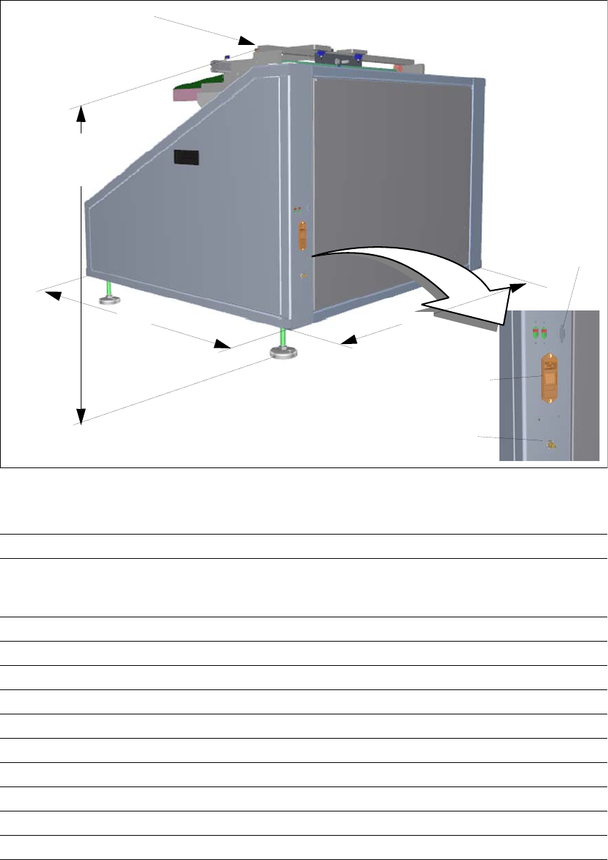
Fig. 3 - 2 SIPLACE Multi-Docking Station – dimensions in millimetres, connections
Length x width 1046 mm x 1120.6 mm
Height (to centring pin) 854 mm at 900 mm PCB transport height
884 mm at 930 mm PCB transport height
904 mm at 950 mm PCB transport height
Weight 216 kg
Compressed-air connection p
min
0.5 MPa (5.0 bar) / p
max
1.0 MPa (10.0 bar)
Compressed-air connection Coupling connector KS 2-M5-A
Flow 5 Nl/min
a
a. Under atmospheric standard conditions at 20°C and 1013 hPa
Supply voltage 88 - 264 V AC
No. of wires / phases 3 / 1
Frequency max. 63 Hz
Rated current max. 2 A
Power 0,23 kW
Protection 2 x 8 A
2
3
1
1046
854
884
904
Height to centring pin
(1) Compressed-air connection
(2) CAN bus port
(3) Power supply socket
1120.6