Operating Manual SIPLACE Multi-Docking Station.pdf - 第28页
4 Operation SIPLACE Multi-Docking-S t ation 4.2 Adjusting the T ransport Height Operating Manual 24 4.1.1 CAN Bus Addresses The CAN bus addresses that can be set are indi cated on the sticker loca ted below the sw itch…
23
SIPLACE Multi-Docking-Station 4 Operation
Operating Manual 4.1 Controls and Indicators
4 Operation
4.1 Controls and Indicators
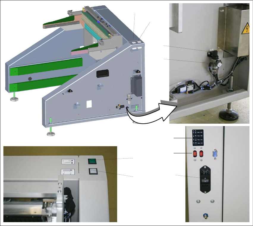
Fig. 4 - 1 SIPLACE Multi-Docking Station – Controls and indicators
(1) Component cart release (white button)
(2) Feeder locking and release (green button)
(3) Knob for setting the operating pressure
(4) Pressure gauge for indicating the operating pressure
(5) Switches S1 and S2 for setting the CAN bus address
(6) Sticker explaining the switches S1 and S2 for CAN bus addressing
(7) Power switch
1
2
3
4
5
7
6
1
2
4 Operation SIPLACE Multi-Docking-Station
4.2 Adjusting the Transport Height Operating Manual
24
4.1.1 CAN Bus Addresses
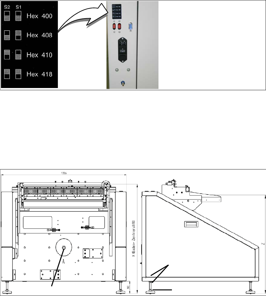
The CAN bus addresses that can be set are indicated on the sticker located below the switches
S1 and S2.
Fig. 4 - 2 CAN bus addresses
4.2 Adjusting the Transport Height
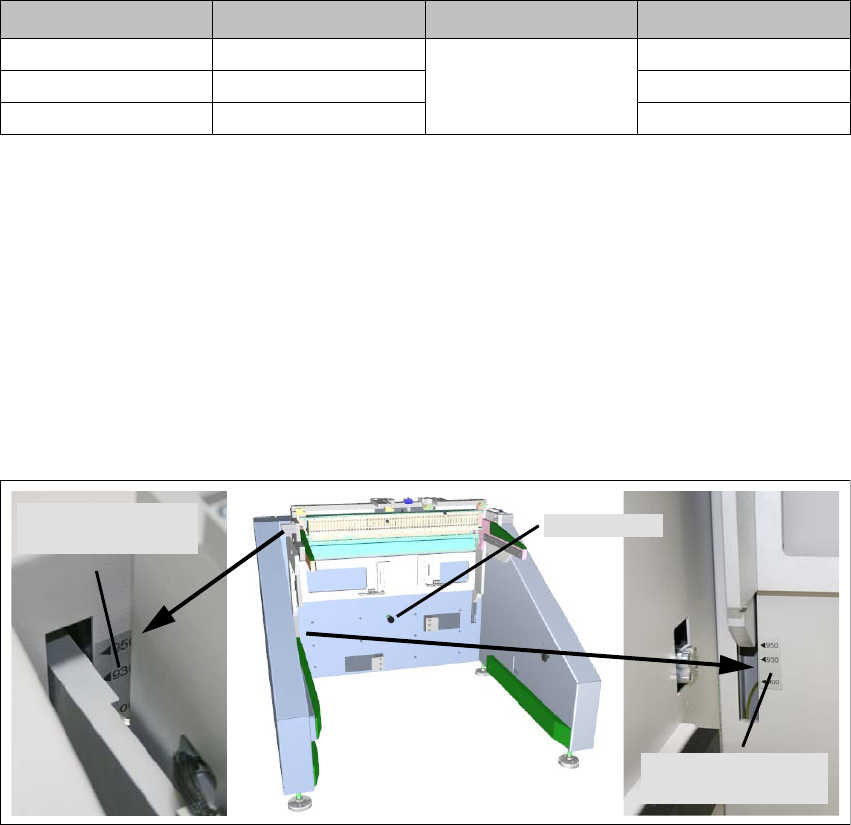
Flat spanners of size SW 22 and SW 24 and a spirit level are required.
Fig. 4 - 3 Adjusting the dimension Y
(1) 2x lock nut SW 24
(2) 1x adjusting screw SW 22
2
1
Detent pin
25
SIPLACE Multi-Docking-Station 4 Operation
Operating Manual 4.2 Adjusting the Transport Height
4.2.1 Adjusting the dimension Y
1. Remove the side cover.
2. Loosen the lock nuts on all adjusting feet.
3. Use the adjusting screws to adjust the dimension Y (see table).
4. Check that the machine is horizontal (using the spirit level).
5. Retighten the lock nuts.
6. Replace the side cover.
4.2.2 Setting the Transport Height
After the dimension Y has been adjusted to the specified value, the transport height can be
adjusted via a detent pin. There are three detent positions and transport height marks indicating
the selected transport height. The mechanical assembly is seated in gas pressure springs, which
facilitates its setting and prevents it from falling down by its own weight.
Fig. 4 - 4 Adjusting the transport height
1. Grab the power and data interface at a suitable position and pull the detent pin.
2. Push or lift the mechanical assembly in the appropriate direction to set the desired transport
height. T
ransport height marks are provided as guides.
3. Be sure to replace the detent pin in its proper position.
Machine height Dimension X Dimension Y Dimension Z
900 mm 854 mm
100 mm
770 mm
930 mm 884 mm 800 mm
950 mm 904 mm 820 mm
Detent pin
Lower transport
height mark
Upper transport
height mark