Operating Manual SIPLACE Multi-Docking Station.pdf - 第27页
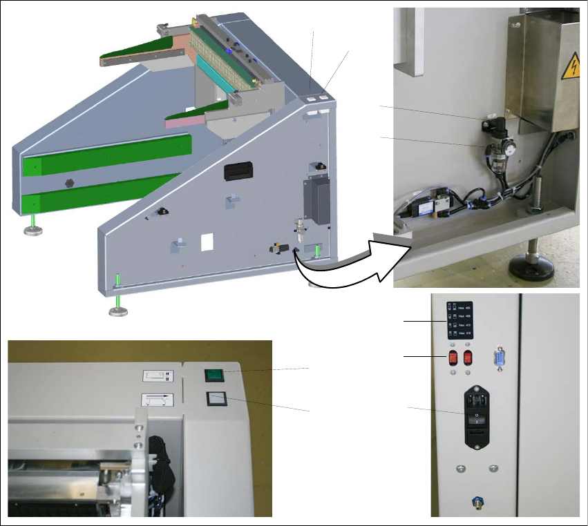
23 SIPLACE Multi-Docking-St ation 4 Operation Operating Manual 4.1 Controls and Indicators 4 Operation 4.1 Controls and Indicators Fig. 4 - 1 SIPLACE Multi-Docking S tation – Controls and indicators (1) Component cart re…
3 Product Description SIPLACE Multi-Docking-Station
3.5 Optional Accessories Operating Manual
22
23
SIPLACE Multi-Docking-Station 4 Operation
Operating Manual 4.1 Controls and Indicators
4 Operation
4.1 Controls and Indicators
Fig. 4 - 1 SIPLACE Multi-Docking Station – Controls and indicators
(1) Component cart release (white button)
(2) Feeder locking and release (green button)
(3) Knob for setting the operating pressure
(4) Pressure gauge for indicating the operating pressure
(5) Switches S1 and S2 for setting the CAN bus address
(6) Sticker explaining the switches S1 and S2 for CAN bus addressing
(7) Power switch
1
2
3
4
5
7
6
1
2
4 Operation SIPLACE Multi-Docking-Station
4.2 Adjusting the Transport Height Operating Manual
24
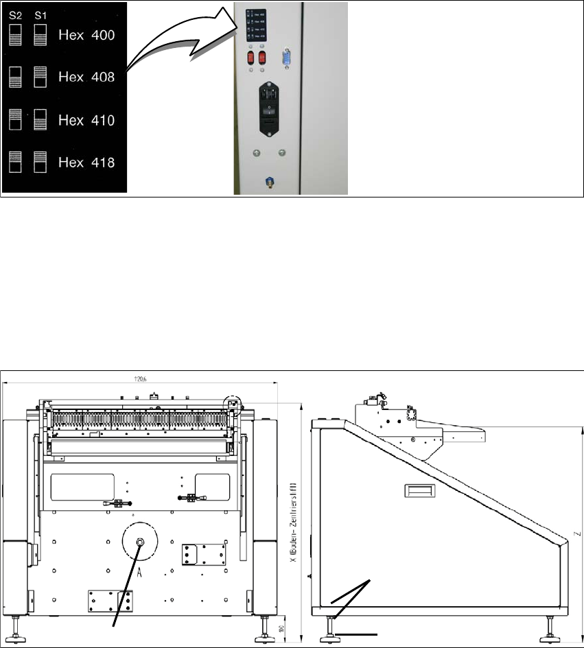
4.1.1 CAN Bus Addresses
The CAN bus addresses that can be set are indicated on the sticker located below the switches
S1 and S2.
Fig. 4 - 2 CAN bus addresses
4.2 Adjusting the Transport Height
Flat spanners of size SW 22 and SW 24 and a spirit level are required.
Fig. 4 - 3 Adjusting the dimension Y
(1) 2x lock nut SW 24
(2) 1x adjusting screw SW 22
2
1
Detent pin