Operating Manual SIPLACE Multi-Docking Station.pdf - 第22页
3 Product Description SIPLACE Multi-Docking-St ation 3.3 Transport Lock Operating Manual 18 3.3 T ransport Lock After un packing and befor e using the docking stat ion for the first time, be sure to remove the transpor…
17
SIPLACE Multi-Docking-Station 3 Product Description
Operating Manual 3.2 Technical Data
3.2 Technical Data
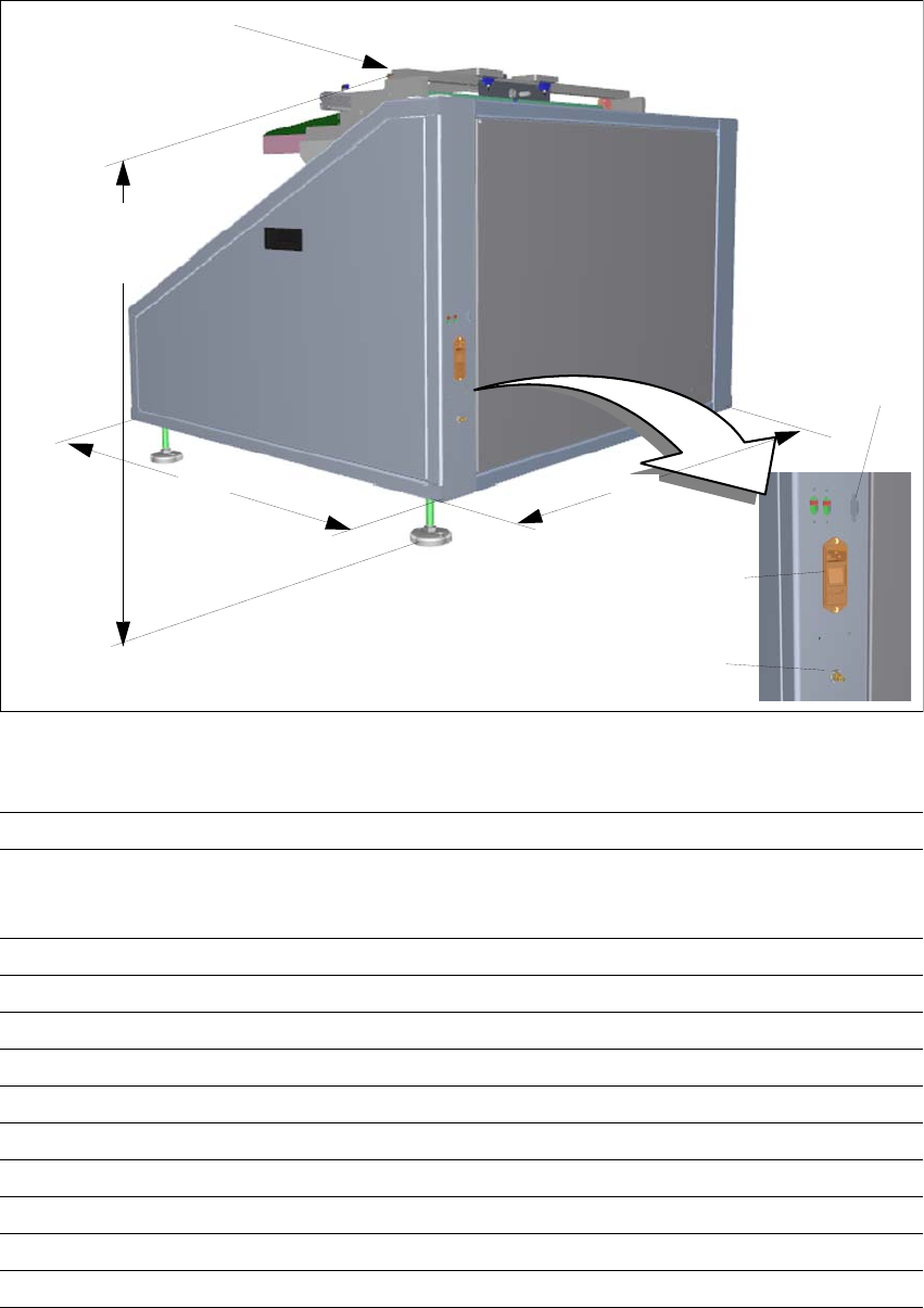
Fig. 3 - 2 SIPLACE Multi-Docking Station – dimensions in millimetres, connections
Length x width 1046 mm x 1120.6 mm
Height (to centring pin) 854 mm at 900 mm PCB transport height
884 mm at 930 mm PCB transport height
904 mm at 950 mm PCB transport height
Weight 216 kg
Compressed-air connection p
min
0.5 MPa (5.0 bar) / p
max
1.0 MPa (10.0 bar)
Compressed-air connection Coupling connector KS 2-M5-A
Flow 5 Nl/min
a
a. Under atmospheric standard conditions at 20°C and 1013 hPa
Supply voltage 88 - 264 V AC
No. of wires / phases 3 / 1
Frequency max. 63 Hz
Rated current max. 2 A
Power 0,23 kW
Protection 2 x 8 A
2
3
1
1046
854
884
904
Height to centring pin
(1) Compressed-air connection
(2) CAN bus port
(3) Power supply socket
1120.6
3 Product Description SIPLACE Multi-Docking-Station
3.3 Transport Lock Operating Manual
18
3.3 Transport Lock
After unpacking and before using the docking station for the first time, be sure to remove the
transport locks.
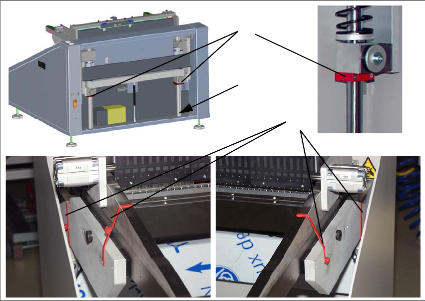
Fig. 3 - 3 Transport locks
(1) 2x shaft transport lock on the lifting axis
(2) 4x side wall transport lock
(3) Storage place for transport locks 1
To loosen the transport lock 1, you
need to remove the rear cover. Loosen the transport lock 1
and fix it loosely to the storage place 3. Replace the cover.
To remove the transport lock 2, cut
the four red cable ties with a suitable tool.
1
2
3
19
SIPLACE Multi-Docking-Station 3 Product Description
Operating Manual 3.4 Installation and Mounting
3.4 Installation and Mounting
To ensure safe operation of the SIPLACE Multi-Docking Station, it must be mounted as described
below.
3.4.1 Mounting Accessories
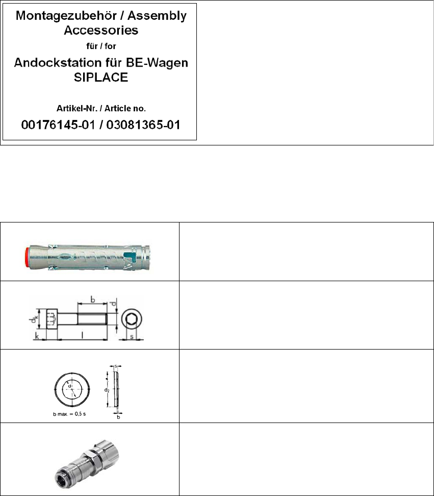
The mounting accessories are provided in a separate package. This package is identified with the
label shown below.
Fig. 3 - 4 Mounting accessories
3.4.1.1 Fastening Parts
Contents:
1. Power cable
2. Fastening parts
4x heavy duty anchor TA M, 12 mm
4x cylinder head screw, DIN EN ISO 4762 M8x80-8.8
4x washer, DIN EN ISO 7090 8.4-140HV
1x female coupling with union nut KD2-CK-4