Operating Manual SIPLACE Multi-Docking Station.pdf - 第30页
4 Operation SIPLACE Multi-Docking-S t ation 4.3 Docking and Undocking the Component Cart Operating Manual 26 4.3 Docking and Undocking the Component Cart Fig. 4 - 5 SIPLACE Multi-Docking St ation (1) Pneumatic cylinder…
25
SIPLACE Multi-Docking-Station 4 Operation
Operating Manual 4.2 Adjusting the Transport Height
4.2.1 Adjusting the dimension Y
1. Remove the side cover.
2. Loosen the lock nuts on all adjusting feet.
3. Use the adjusting screws to adjust the dimension Y (see table).
4. Check that the machine is horizontal (using the spirit level).
5. Retighten the lock nuts.
6. Replace the side cover.
4.2.2 Setting the Transport Height
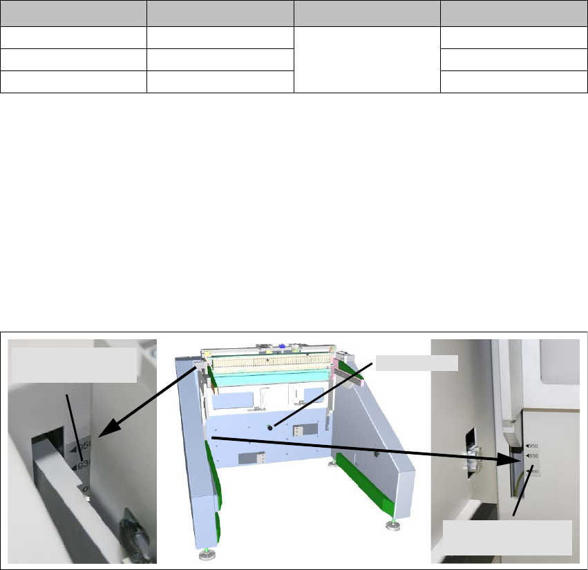
After the dimension Y has been adjusted to the specified value, the transport height can be
adjusted via a detent pin. There are three detent positions and transport height marks indicating
the selected transport height. The mechanical assembly is seated in gas pressure springs, which
facilitates its setting and prevents it from falling down by its own weight.
Fig. 4 - 4 Adjusting the transport height
1. Grab the power and data interface at a suitable position and pull the detent pin.
2. Push or lift the mechanical assembly in the appropriate direction to set the desired transport
height. T
ransport height marks are provided as guides.
3. Be sure to replace the detent pin in its proper position.
Machine height Dimension X Dimension Y Dimension Z
900 mm 854 mm
100 mm
770 mm
930 mm 884 mm 800 mm
950 mm 904 mm 820 mm
Detent pin
Lower transport
height mark
Upper transport
height mark
4 Operation SIPLACE Multi-Docking-Station
4.3 Docking and Undocking the Component Cart Operating Manual
26
4.3 Docking and Undocking the Component Cart
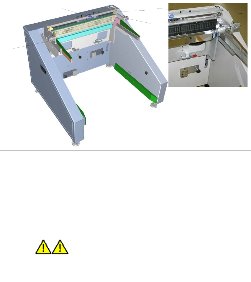
Fig. 4 - 5 SIPLACE Multi-Docking Station
(1) Pneumatic cylinder for locking the component cart
(2) Sensor for component cart detection
(3) Centring pin
4.3.1 Docking the SIPLACE SX Component Cart to the Multi-Docking Station
WARNING
Do not reach between the areas between the component cart and the SIPLACE Multi-Docking
Station during docking.
– Push the component cart into the docking station until it is locked by the pneumatic cylinders.
– The two buttons will flash shortly. If the component cart is properly locked, the w
hite button
(component cart release) will be lit permanently.
– If the component cart is not locked properly, the
white button will be flashing.
– If the feeders are locked properly, the green feeder
locking button will be lit.
2
1
1
3
27
SIPLACE Multi-Docking-Station 4 Operation
Operating Manual 4.4 Conversion to COT 30 or COT 40
4.3.2 Undocking the SIPLACE SX Component Cart from the Multi-Docking Station
WARNING
Do not reach between the areas between the component cart and the SIPLACE Multi-Docking
Station during docking.
– Undocking the component cart requires that the feed be locked.
Make sure that the green feeder lock
ing button is lit.
– Push the white component cart release button. The component c
art will be released.
– Pull the component cart from the re
ar out of the docking station.
4.4 Conversion to COT 30 or COT 40
DANGER
Prior to converting the SIPLACE Multi-Docking Station, be sure to switch it o
ff at the main power
switch and disconnect the power cord from the power supply.