Operating Manual SIPLACE Multi-Docking Station.pdf - 第33页
29 SIPLACE Multi-Docking-St ation 4 Operation Operating Manual 4.4 Conversion to COT 30 or COT 40 4.4.2 Adapter COT 30 – Option Fig. 4 - 7 SIPLACE Multi-Docking S tation – COT 30 (1) Guide strip (2) Angle bracket COT 30 …
4 Operation SIPLACE Multi-Docking-Station
4.4 Conversion to COT 30 or COT 40 Operating Manual
28
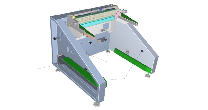
4.4.1 Standard COT 60
Fig. 4 - 6 SIPLACE Multi-Docking Station – COT 60
(1) Guide strip used for options COT 30 and COT 40.
(2) Star knob screws for securing the angle brackets
to the sides on the options COT 30 and
COT 40.
(3) Star knob screws for securing the guide strip and
the angle bracket on the guide strip.
1
2
3
29
SIPLACE Multi-Docking-Station 4 Operation
Operating Manual 4.4 Conversion to COT 30 or COT 40
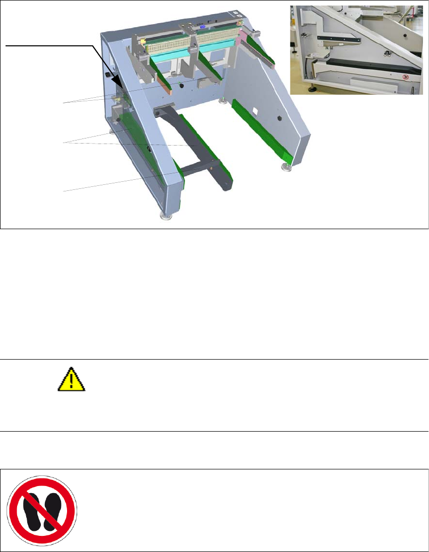
4.4.2 Adapter COT 30 – Option
Fig. 4 - 7 SIPLACE Multi-Docking Station – COT 30
(1) Guide strip
(2) Angle bracket COT 30
(3) Skid strip COT 30
The items (2) and (3) are included in the mounting accessories with part number 00176146-01.
CAUTION
Do not stand on the guide strip or apply loads from
above or below. This will damage the guide
strip and its retainer.
1
3
2
Storage space for
the COT 30
accessories.
Keep off
Label locations: On the SIPLACE Multi-Docking Station
- Guide strip, on top and bottom sides.
Number per machine: 2
4 Operation SIPLACE Multi-Docking-Station
4.4 Conversion to COT 30 or COT 40 Operating Manual
30
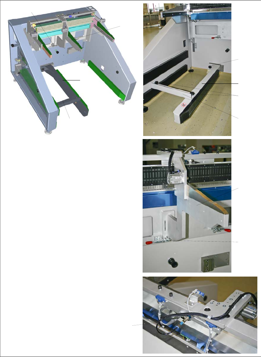
4.4.2.1 Conversion to COT 30
1
3
6
5
7
(1) Switch off the Multi-Docking Station
and disconnect the power cable
from the power supply.
(2) Insert the guide strip 1 into the
retainer at the bottom and tighten
the star knob screw 2.
(3) Install the angle bracket 3 as shown
and tighten the two star knob
screws 4.
(4) Open the quick clamp 5, hook in the
skid strip 6 and close the quick
clamp.
(5) Make the proper connections to the
COT 30 adapter 7.
(6) Check that all the steps have been
executed completely and correctly.
1
2
3
4
5
6