TS5622VU-DVD.pdf - 第9页
9 8.2 TO CHANGE THE DIAPHRAGM Tool required: Flat tip screwdriver, Snap ring flier, 7/64” hex wrench. 1. Remove needle retaining cap (12) then remove the dispense needle. 2. Remove the two socket head cap sc rews (7) fro…

8
8. MAINTENANCE AND CLEANING
Normally, purging the valve with appropriate flush material or solvent after use is sufficient for
cleaning. However some material may cause a buildup in the valve chamber, in this case periodic and
thorough cleaning will be required.
8.1 CLEANING
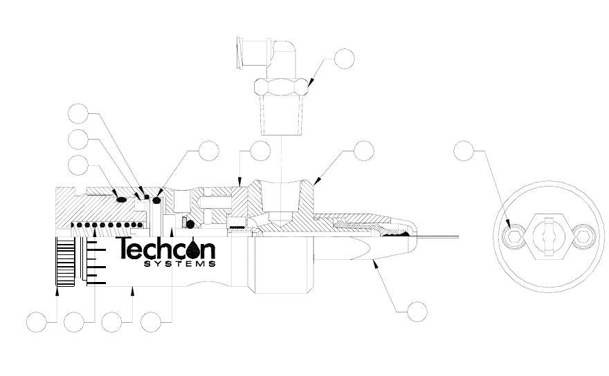
Refer to figure 6.0
1. Release fluid pressure
2. Disconnect fluid line
3. Disconnect valve air line
4. Remove needle retaining cap (12) then remove the dispense needle.
5. Remove the two socket head cap screws (7) from the fluid housing (6)
6. Pull the fluid housing away from the air cylinder assembly (10)
7. Clean Diaphragm (5) and fluid housing (6)
8. Reinstall the fluid housing (6).
9. Align the fluid housing mounting holes with diaphragm and air cylinder holes.
10. Reinsert the two socket head cap screws (1) and hand tightens them only. Do not exceed 14 in lb
(1.58 N-m) torque.
CAUTION: Make sure the fluid pressure is released before disassemble the valve.
NOTE: Avoid using sharp probes for cleaning. Any nicks or scratches on the
diaphragm or the sealing area of the fluid housing may cause leakage.
9
8.2 TO CHANGE THE DIAPHRAGM
Tool required: Flat tip screwdriver, Snap ring flier, 7/64” hex wrench.
1. Remove needle retaining cap (12) then remove the dispense needle.
2. Remove the two socket head cap screws (7) from the fluid housing (6)
3. Pull the fluid housing away from the air cylinder assembly (10)
4. Remove the old diaphragm (5) by unscrew it in the counterclockwise direction.
5. Install the new diaphragm by threading it in the clockwise direction. Make sure the internal
thread on the diaphragm is not stripped or cross-threaded.
6. Hand tightened the diaphragm until it bottoms out against shoulder on piston rod. At this point,
do not over tighten or loosen the diaphragm to align the diaphragm and air cylinder holes.
7. The valve is designed so that the fluid housing can be rotated in 45° increments to allow for
material input/output alignment. To align the holes of the diaphragm with the appropriate holes
in the air cylinder body, insert a small flat tip screwdriver through the hole in the stroke control
knob (8) and engage the piston rod slot. Turn the screwdriver clockwise to rotate the rod, piston
and diaphragm assembly until the appropriate holes are lined up.
8. Reinstall the fluid housing (6).
9. Align the fluid housing mounting holes with diaphragm and air cylinder holes.
10. Reinsert the two socket head cap screws (7). Do not exceed 14 in lb (1.58 N-m) torque.
10
8.3 TO CHANGE OR LUBRICATE PISTON O-RING
1. Remove the fluid housing (6).
2. Remove the diaphragm (5).
3. Remove the stroke control knob (8) and spring (9).
4. Remove the retainer ring (2) and anti-rotating washer (1).
5. Remove the piston assembly (11).
6. Replace O-ring (4) if damaged; otherwise lubricate O-ring with O-ring grease.
7. Reinstall piston, retainer ring and anti-rotating washer.
8. Reinstall spring and stroke control knob.
9. Reinstall diaphragm and fluid housing.
810911
12
2
3
1
4 5 67
13
Figure 6.0