F5HM Circuit Diagrams.pdf - 第10页
SIPLACE F5 HM Detail ed Circuit Di agram Fol der 01/2001 U S Edition 0 Drawing Number ing System 10 'UDZ LQJ1X PEHULQJ 6\VWHP / HJ HQG H6 \PER OV $ UWHQY RQ6WU|P HQXQG6S DQQXQ JHQ.LQG RIFXU…
SIPLACE F5 HM Detailed Circuit Diagrams Folder
01/2001 US Edition
Table of Contents 9
:3&)
00319890-020101LD3 Overview. . . . . . . . . . . . . . . . . . . . . . . . . . . . . . . . . . . . . . . . . . . . . . . . . . . . . . . . . . 148
00302827-020201LD3 Control unit / servo unit. . . . . . . . . . . . . . . . . . . . . . . . . . . . . . . . . . . . . . . . . . . . . . . 149
00302852-030101LD3 Control of servo boards and brake . . . . . . . . . . . . . . . . . . . . . . . . . . . . . . . . . . . . . . 150
00320064-030101LD3 Power supply (Sh. 1 of 4) . . . . . . . . . . . . . . . . . . . . . . . . . . . . . . . . . . . . . . . . . . . . . 151
00320064-030101LD3 EMERG.-STOP circuit (Sh. 2 of 4) . . . . . . . . . . . . . . . . . . . . . . . . . . . . . . . . . . . . . . 152
00320064-030101LD3 Mounting plate, distributor inputs (Sh. 3 of 4). . . . . . . . . . . . . . . . . . . . . . . . . . . . . . 153
00320064-030101LD3 Mounting plate, ground terminals (Sh. 4 of 4). . . . . . . . . . . . . . . . . . . . . . . . . . . . . . 154
00302827-020101ZD1 Control unit / servo unit. . . . . . . . . . . . . . . . . . . . . . . . . . . . . . . . . . . . . . . . . . . . . . . 155
00320064-030101MD1 Design of mounting plate . . . . . . . . . . . . . . . . . . . . . . . . . . . . . . . . . . . . . . . . . . . . . 156
SIPLACE F5 HM Detailed Circuit Diagram Folder
01/2001 US Edition
0 Drawing Numbering System 10
'UDZLQJ1XPEHULQJ6\VWHP
/HJHQGH6\PEROV
$UWHQYRQ6WU|PHQXQG6SDQQXQJHQ.LQGRIFXUUHQWDQGYROWDJH
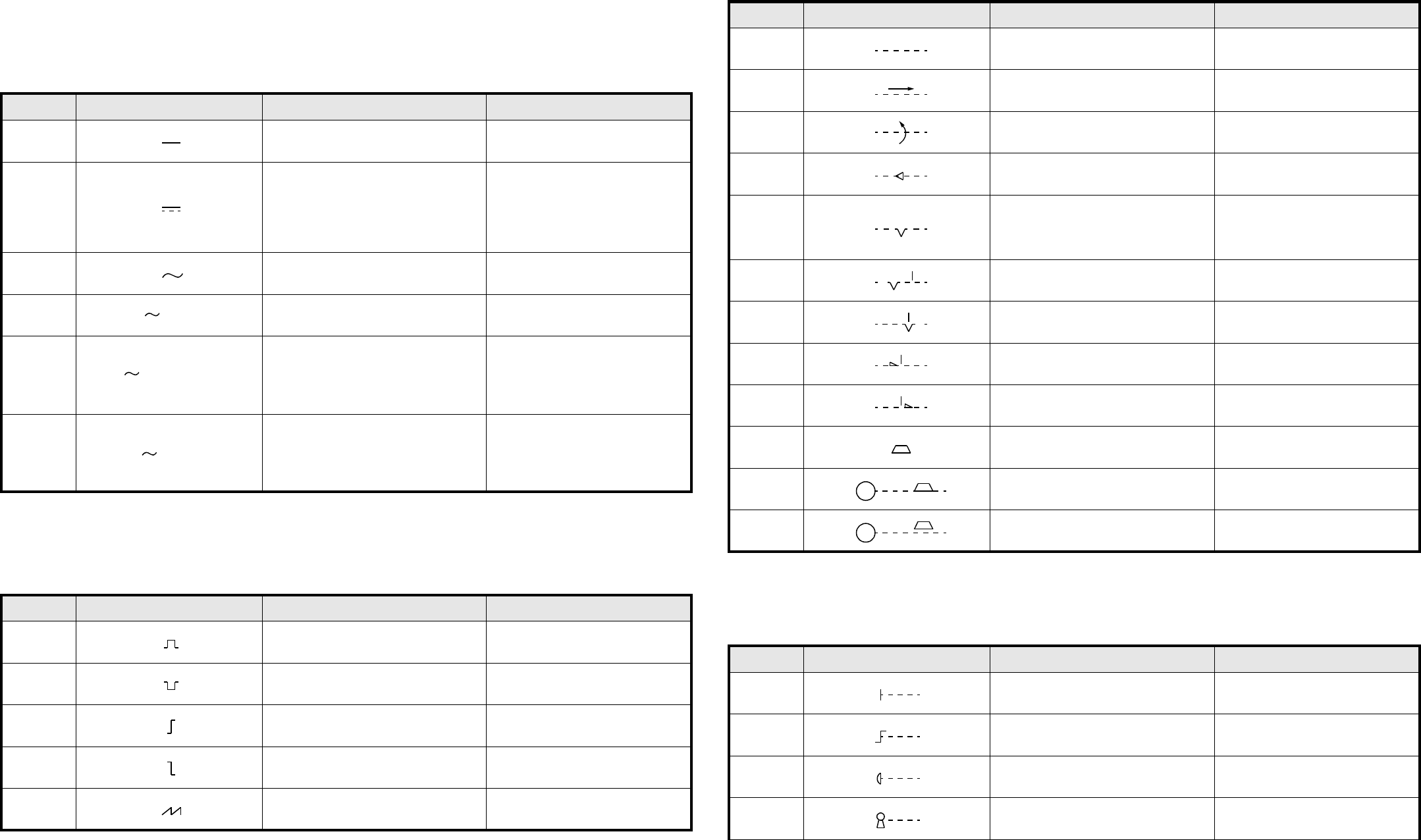
,PSXOVIRUPHQ6LJQDOZDYHIRUPV
0HFKDQLVFKH6WHOOWHLOH0HFKDQLFDOFRQWUROV
$QWULHEVDUWHQ2SHUDWLQJGHYLFHVDQGPHWKRGV
1U1R 6FKDOW]HLFKHQ6\PERO %HVFKUHLEXQJ 'HVFULSWLRQ
02-02-01 Gleichstrom Direct current
02-02-03
Gleichstrom
$QPHUNXQJ
Das Schaltzeichen 02-02-03 muß ange-
wendet werden, wenn das Schaltzei-
chen 02-02-01 zu Verwechslungen
führt.
Direct current
1RWH
Symbol 02-02-03 is to be used if
symbol 02-02-01 causes confusion.
02-02-04 Wechselstrom Alternating current
02-02-05 Wechselstrom, 50 Hz Alternating current of 50 Hz
02-02-07
Dreiphasen-Vierleitersystem mit drei
Außenleitern und einem Neutralleiter,
50 Hz, 400 V (230 V zwischen jedem
Außenleiter und dem Neutralleiter).
3N darf durch 3/N ersetzt werden.
Alternating current: three-phase
with neutral, 50 Hz, 400 V (230 V
between phase and neutral).
3N may be replaced by 3 + N.
02-02-08
Dreiphasen-Fünfleitersystem mit drei
Außenleitern, einem Neutralleiter und
einem Schutzleiter, 50 Hz, direkte
Erdung eines Punktes, Neutral- und
Schutzleiter getrennt.
Alternating current, three-phase, 50
Hz: system having one point directly
earthed and separate neutral and
protective conductors throughout.
1U1R 6FKDOW]HLFKHQ6\PERO %HVFKUHLEXQJ 'HVFULSWLRQ
02-10-01 Positiver Impuls Positive-going pulse
02-10-02 Negativer Impuls Negative-going pulse
02-10-04 Positive Schrittfunktion Positive-going step function
02-10-05 Negative Schrittfunktion Negative-going step function
02-10-06
Sägezahn Saw-tooth
50 Hz
3N 50 Hz 400/230 V
3/N/PE 50 Hz / TN - S
1U1R 6FKDOW]HLFKHQ6\PERO %HVFKUHLEXQJ 'HVFULSWLRQ
02-12-01 Wirkverbindung, allgemein Mechanical connection (link)
02-12-02
Mechanische Verbindung mit Angabe
der Richtung von Kraft oder Bewegung
Mechanical connection with indica-
tion of direction of force or motion
02-12-03
Mechanische Verbindung mit Angabe
der Drehrichtung
Mechanical connection with indica-
tion of direction of rotation
02-12-07 Selbsttätiger Rückgang Automatic return
02-12-08
Raste
Nicht selbsttätiger Rückgang
Einrichtung zum Beibehalten einer
gegebenen Stellung
Detent
Non-automatic return
Device for maintaining a given posi-
tion
02-12-09 Raste, nicht eingerastet Detent, disengaged
02-12-10 Raste, eingerastet Detent, engaged
02-12-12 Sperre, nicht verklinkt Latching device, disengaged
02-12-13 Sperre, verklinkt Latching device, engaged
02-12-20 Bremse Brake
02-12-21 Elektromotor mit eingelegter Bremse Electric motor with brake applied
02-12-22 Elektromotor mit gelöster Bremse Electric motor with brake released
1U1R 6FKDOW]HLFKHQ6\PERO %HVFKUHLEXQJ 'HVFULSWLRQ
02-13-01 Handantrieb, allgemein
Manually operated control,
general symbol
02-13-04 Betätigung durch Drehen Operated by turning
02-13-08 Notschalter
Emergency switch (mushroom-head
safety feature)
02-13-13 Betätigung durch Schlüssel Operated by key
M
M
SIPLACE F5 HM Detailed Circuit Diagram Folder
01/2001 US Edition
0 Drawing Numbering System 11
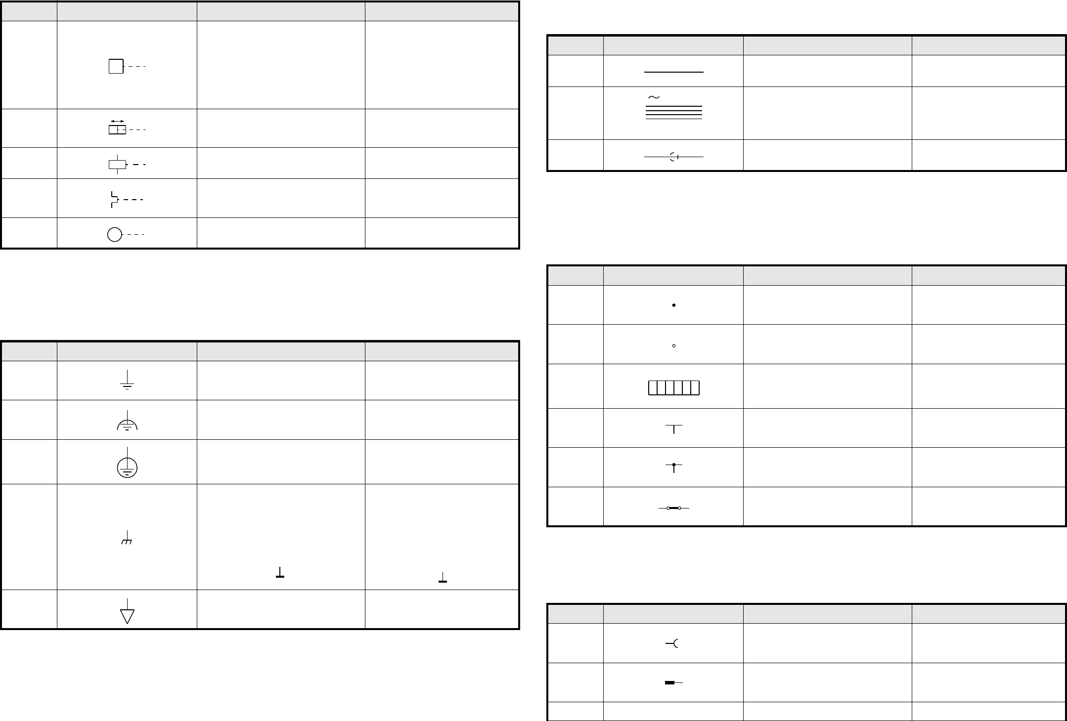
(UGH0DVVHbTXLSRWHQWLDO
(DUWKDQGIUDPHFRQQHFWLRQVHTXLSRWHQWLDOLW\
/HLWHU&RQGXFWRUV
$QVFKOVVHXQG/HLWHUYHUELQGXQJHQ
7HUPLQDOVDQGFRQQHFWLRQVRIFRQGXFWRUV
9HUELQGHU&RQQHFWLQJGHYLFHV
1U1R 6FKDOW]HLFKHQ6\PERO %HVFKUHLEXQJ 'HVFULSWLRQ
02-13-20
Kraftantrieb, allgemein
Betätigung durch gespeicherte mecha-
nische Energie
$QPHUNXQJ
Hinweise auf die Art der gespeicherten
Energie dürfen in das Quadrat eingetra-
gen werden (z. B. Formelzeichen nach
DIN 1304).
Drive, general symbol
Operated by stored mechanical
energy
1RWH
Information showing the form of
stored energy may be added in the
square.
02-13-22
Betätigung durch pneumatische oder
hydraulische Steuerung in beiden Rich-
tungen
Operated by pneumatic or hydraulic
control, double acting
02-13-23
Betätigung durch elektromagnetischen
Antrieb
Operated by electromagnetic actua-
tor
02-13-25
Betätigung durch thermischen Antrieb,
z. B. Bimetallrelais
Thermischer Überstromschutz
Operated by thermal actuator, for
example thermal relay, thermal
overcurrent protection
02-13-26 Betätigung durch Motor Operated by electric motor
1U1R 6FKDOW]HLFKHQ6\PERO %HVFKUHLEXQJ 'HVFULSWLRQ
02-15-01 Erde, allgemein
Earth, general symbol
Ground, general symbol
02-15-02 Fremdspannungsarme Erde
Noiseless earth
Noiseless ground
02-15-03 Schutzerde
Protective earth
Protective ground
02-15-04
Masse
Gehäuse
$QPHUNXQJ
Die Schraffur darf entfallen, wenn keine
Unklarheit besteht. Die Linie, die das
Gehäuse repräsentiert, muß dann brei-
ter dargestellt werden:
Frame
Chassis
1RWH
The hatching may be completely or
partly omitted if there is no ambigu-
ity. If the hatching is omitted, the line
representing the frame or chassis
shall be thicker as shown below:
02-15-05 Äquipotential Equipotentiality
M
1U1R 6FKDOW]HLFKHQ6\PERO %HVFKUHLEXQJ 'HVFULSWLRQ
03-01-01 Leiter Conductor
03-01-05
Dreiphasen-Vierleitersystem mit drei
Außenleitern und einem Neutralleiter,
50 Hz, 400 V, Außenleiter 120 mm
2
,
Neutralleiter 50 mm
2
Three-phase circuit, 50 Hz, 400 V,
three conductors of 120 mm
2
, with
neutral of 50 mm
2
03-01-07 Leiter, geschirmt Screened conductor
1U1R 6FKDOW]HLFKHQ6\PERO %HVFKUHLEXQJ 'HVFULSWLRQ
03-02-01 Verbindung von Leitern Connection of conductors
03-02-02
Anschluß (z. B. Klemme)
$QPHUNXQJ
Der Kreis darf ausgefüllt werden.
Ter mi na l
1RWH
The circle may be filled in.
03-02-03
Anschlußleiste, dargestellt mit
Anschlußbezeichnungen
Terminal strip, example shown with
terminal markings
03-02-04 Abzweig von Leitern Junction of conductors
03-02-05 Abzweig von Leitern Junction of conductors
03-02-08 Leiter-Verbindungsstück Conductor joint
1U1R 6FKDOW]HLFKHQ6\PERO %HVFKUHLEXQJ 'HVFULSWLRQ
03-03-01
Buchse
Pol einer Steckdose
Socket (female)
Pole of a socket
03-03-03
Stecker
Pol eines Steckers
Plug (male)
Pole of a plug
3N 50 Hz 400 V
3 x 120 x 1 x 50
1112 15161314