F5HM Circuit Diagrams.pdf - 第17页
1 Detailed Circuit Diagr ams 17 1 Detailed Circuit Diagrams NOTF5HM1 Emerg.-stop circuit, SIPLACE F 5 HM 00322069- xx lbl 00322069- xx br Compone nt table, le fthand side 1a 00322063-x x/X37a 2c 00322063-x x/X37a for mac…

SIPLACE F5 HM Detailed Circuit Diagram Folder
01/2001 US Edition
0 Drawing Numbering System 16
6WUXFWXUHRIWKH7HFKQLFDO1XPEHULQJ6\VWHP
'RFXPHQWQXPEHU
A document number consists of an item number, product status, document status, document type, language and for-
mat.
,WHPQXPEHU
An item number consists of master number and function status
)XQFWLRQVWDWXV)6 YHUVLRQVUHOHYDQWWRIXQFWLRQ
All documents pertaining to an item number have the same functions status. The versions of a product relevant to func-
tion are determined by the totality of the features describing the function and documented in the corresponding docu-
mentation.
3URGXFWVWDWXV36
The versions of a product not relevant to function are determined by the totality of the remaining features (no features
with relevance to function) and documented in the corresponding documentation.
'RFXPHQWVWDWXV'6
The status of the contents of a technical document.
'RFXPHQWW\SH
/DQJXDJH
)RUPDW
Document number
Item number
Example = '
Pattern
11111111
11 11 11
$$1
Main number S FS PS DS DT L F
Separator = - for standard part
Separator = S for service part
Function status as per SN 10370, Part 1
Product status as per SN 10370, Part 1
Document status as per SN 10370, Part 1
Document type
Language
Format
N = Numerical counting position
A = Alphabetic counting position
A Installation diagram, electrical B Construction specifications, electrical
E
Adjustment specifications, testing and inspection
instructions, setting specifications
F Movement diagram, general functions drawing
G Machine identification plate K Terminal diagram, cable diagram, wires list
L Circuit Diagram M Assembly diagram, installation diagram, mechanical
N Master pattern, layout, inscription P Program documentation
R Product description S Parts list
T Parts drawing U Documentation overview
V Construction specifications, mechanical W Hydraulics diagram
X Pneumatics diagram Z Assembly, mechanical
D German E English
F French I Italian
N Dutch S Spanish
X German/English Y German/Italian
0A0 1 A1
2A2 3 A3
4A4
1 Detailed Circuit Diagrams 17
1 Detailed Circuit Diagrams
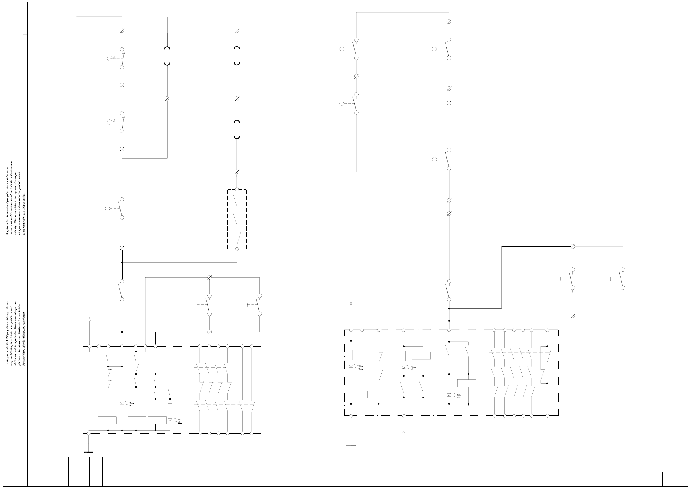
NOTF5HM1 Emerg.-stop circuit, SIPLACE F5 HM
00322069-xx lbl
00322069-xx br
Component table, lefthand side
1a 00322063-xx/X37a
2c 00322063-xx/X37a
for machine ’ON’
software release signal
Monitoring
for machine ’ON’
software release signal
Monitoring
00336812-xx K3
54
53
00336812-xx K1
00321529-xx S4
X211/8
X211/7
To power supply
Output conveyor
Input conveyor
unit
Safety protection
00336812-xx K2
Safety protection
00336812-xx K1
unit
EMERG.-STOP
EMERG.-STOP
AenderungZustand Datum
CAD-Datei : NOTF5HM-1.DWG
Urspr./Ers.f./Ers.d.NormName
Gepr.
Stromlaufplan/Circuit diagram
PL EA
Mat.-Nr. :
Beab. Hi
Datum 08.01.2001
SIEMENS
Sh.
Sh.
SMD Placement System SIPLACE F5 HM
1
2
EMERG.-STOP circuit
SIPLACE F5 HM
H2’: LED ready
L2
H1’: LED release
H1’
3414
24
44
58
K2’
K1’
K1’
K3’
H2’
K2’
L1
K1’
X1 X2 X3
24V AC
K3’
K2’
K3’
K1’ K3’
K1’
K2’K1’
X5
K3’
X4 X6
33
13
23 43 57
66
65
H3: LED channel 1
H2+H3 = releasePOWER SUPPLY
H1: LED MAIN
UNIT
L2
X6
H2: LED channel 2
14
54
34
24
44
66
K1’
K2’
H1
L1
K3’
X1 X4
K3’K1’
H3
H2
K1
X3
K3’
K1’
24V AC
K2’K2’
K1’
K2’
K2’
X5
K3’
13 53
3323
43
65
conveyor conveyor
ONON
OPTION: Cover switch, succeeding machine (00321421-xx)
Connect cable 00305817-xx to X211/13 gn - X211/14 ye
Warning: If you install the option
remove jumper X211/13 - X211/14.
remove jumper X211/11 - X211/12.
Warning: If you install the option
Connect cable 00305816-xx to X211/11 gn - X211/12 ye
OPTION: Cover switch, preceding machine (00321421-xx)
00344266-xx
push-buttonpush-button
conveyor conveyor
X211 terminal strip (lefthand side)
Note:
00321432-xx pk
00321432-xx gr
00321113-xx ye
00321434-xx pk
00321434-xx gr
00321113-xx gn
input
push-button
output
push-button
00321528-xx S2
4
33
4
X211/16
X211/17
00321529-xx S2
00321113-xx bl
14
13
00305818-xx ye
00305818-xx gn
X211/14
X211/13
22
21
X211/12
Output conveyor
00303617-xx S1
switch
Protective cover
X211/10
21
22
X211/11
X211/9
21
22
21
22
00305815-xx ye
00305815-xx gn
00321573-xx gn
00321573-xx ye
00321574-xx gn
00321574-xx ye
00303614-xx S1
Input conveyor
switch
Protective cover
Protective cover
switch
switch
Protective cover
00321417-xx S1
lefthand side
righthand side
00322070-xx lbl
00322070-xx br
00322112-xx ye
00322112-xx gn
Component table, righthand side
WPC interface, righthand side
00321436-xx br
00321436-xx wh
00321433-xx br
00321433-xx wh
00336812-xx +24VDC
00321113-xx wh & br
push-button
push-button
00321529-xx S1
00321528-xx S1
X211/4
2
1
X211/3
2
1
X211/2
00321416-xx S1
X211/6
3c 00322105-xx/X57
4c 00322105-xx/X57
X211/5
1a 00322064-xx/X37b
2c 00322064-xx/X37b
00321113-xx bk
00321434-xx brgn
00321434-xx whye
00321113-xx vio
4
3
X211/15
switch
Key-operated
00321113-xx rdbl
00321432-xx ye
00321432-xx gn
4
3
4
3
00321434-xx ye
00321434-xx gn
00321113-xx grpk
X211/19
X211/18
44
43
00336812-xx K3
00321528-xx S2
ON
input
00321529-xx S2
output
ON
1 Detailed Circuit Diagrams 18
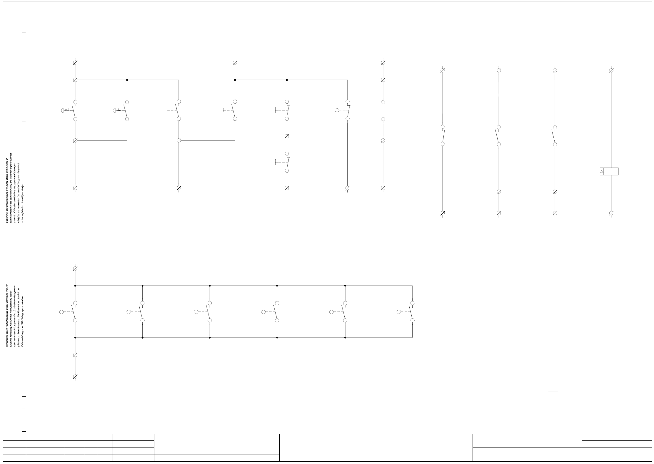
NOTF5HM2 Emerg.-stop circuit - signaling circuit, SIPLACE F5 HM
(S5 input) (S5 input)
1
2
(S5 input)
Key-operated
switch
00321529-xx S4
Push-button
(S5 input)
EMERG.-STOP EMERG.-STOP
X2KD + (+24VDC)
X2KC/M (S5 output)
X2KD/2
blbk
X210/1
6c
X210/2
5c
blbk
(S5 input)
EMERG. STOP
WPC interface, righthand side
00322112-xx pk
00322105-xx X57
00322112-xx gr
2KD + (+24VDC)
00322105-xx X57
SMD Placement System SIPLACE F5 HM
2
2
EMERG.-STOP circuit - signaling circuit
SIPLACE F5 HM
00344266-xx
Signaling circuit Signaling circuit Signaling circuit Signaling circuit
blbk blbk
monitoring of control ON and software release signal
Signaling circuits
Cover switch signaling circuit
EMERG.-STOP signaling circuits, ON/OFF push-buttons, key-operated switches
blbk
Cover open
X2KD/3 (S5 input)
machine
(Option)
00321421-xx S1 00321421-xx S1
(Option)
machine
Push-button Push-button Push-button
blbk
4
3
4
3
4
3
4
3
2
11
2
blbk blbk
Off button
00321432-xx vi
00321432-xx bk
Key-operated switch
00321434-xx bk
00321434-xx vi00321434-xx grpk
rdrd
00321434-xx rd
input conveyor
OFF
output conveyor
OFF
X2KD/6
X210/5
X2KD/5
00321528-xx S3
00321529-xx S3
X210/4
X2KD/4X2KD/2
X210/2
X210/1
X2KD + (+24VDC)
00321529-xx S200321528-xx S200321529-xx S100321528-xx S1
On buttonEMERG. STOP
00321433-xx ye 00321436-xx ye 00321432-xx grpk
00321432-xx rd00321436-xx gn00321433-xx gn
ONON
output conveyorinput conveyoroutput conveyor
push-button
input conveyor
push-button
X2KD+ (+24VDC)
X210/3
00321416-xx S1
00321417-xx S1 00321614-xx S1
14
1313
1414
13
00305818-xx wh
00305818-xx br
Cover protective
switch
output conveyor
00305817-xx br
00305817-xx wh
13
14
00303617-xx S1
13
14
00336812-xx K3
A2
A1
00336812-xx K1 00336812-xx K1
43
44
X211/21
X2KD/8 (S5 input)X2KD/1 (S5 input)
X211/22
58
57
+ 24VDC+ 24VDC
X2KB/7 (S5 input)
00336812-xx K3
22
21
+ 24VDC X2KC/8 (S5 output)
X212/4X212/4X212/4
K1
00321113-xx grbr00321113-xx whgn00321113-xx whye00321113-xx whye
00321113-xx brgn00321113-xx yebr00321113-xx whgr
Software release
Monitoring K2
Control OnControl On
Monitoring K3
Software release
X212 terminal strip (lefthand side)
X211 terminal strip (lefthand side)
X210 terminal strip (lefthand side)
Note:
13
14
Cover protective
lefthand side
switch
Cover protective
00321573-xx br
switch
righthand side
00321573-xx wh 00321574-xx wh
00321574-xx br
Cover protective
input conveyor
switch
preceding
switch
Cover protective
00305815-xx br
00305815-xx wh 00305816-xx wh
00305816-xx br
Cover protective
switch
succeeding
AenderungZustand Datum
CAD-Datei : NOTF5HM-2.DWG
Urspr./Ers.f./Ers.d.NormName
Gepr.
Stromlaufplan/Circuit diagram
PL EA
Mat.-Nr. :
Beab. Hi
Datum 08.01.2001
SIEMENS
Sh.
Sh.