F5HM Circuit Diagrams.pdf - 第30页
1 Detailed Circuit Diagr ams 30 LP01-F 5HM PCB conveyo r 1 + 2, power supp ly Aend erung Zust and Datu m CAD-Datei : LP1-F5HM.DWG Urspr./Ers .f./Ers.d. Norm Name Gepr. Strom laufpla n/Circu it di agra m PL EA Mat.-Nr. : …
1 Detailed Circuit Diagrams 29
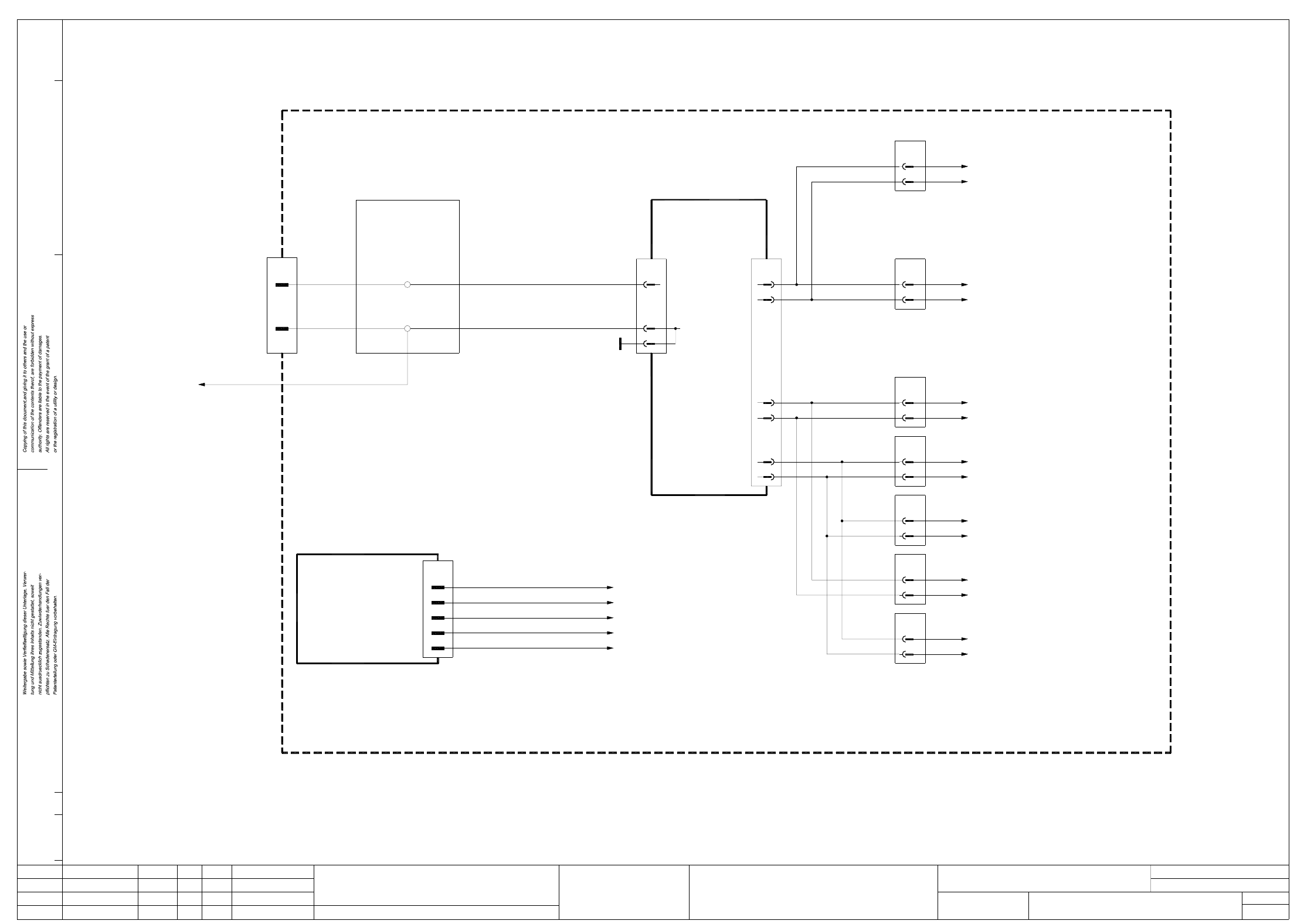
SERVF5HM2 Power supply unit for servo amplifier, anti-crash board, SIPLACE F5 HM
30V unswitched
Starpoint 007
1L-, GND
GND
+30V
C0510-W1 (cable)
righthand side
To terminal strip
X207:19
00337333-xx
A10
Anti-crash board
+24V2
5
4
3
-15V
+5V
GND
1
X11g
+15V
blbk
pkgr
grbk
wh
pkbk
To pin 4 of power supply unit A12
To pin 18 of power supply unit A12
To star point 007
To star point 006
To star point 004
AenderungZustand Datum
CAD-Datei : SERVF5HM2.DWG
Urspr./Ers.f./Ers.d.NormName
Gepr.
Stromlaufplan/Circuit diagram
PL EA
Mat.-Nr. :
Beab. Hi
Datum 08.01.2001
SIEMENS
Sh.
Sh.
SMD Placement System SIPLACE F5 HM
2
2
Power supply for servo amplifier,
anti-crash board, SIPLACE F5 HM
Backplane A19, Z axis, pick&place head
X4vd
pkbk
pkgr
-15V
+15V1
2
Backplane A18, DR axis, pick&place head
X4vr
pkbk
pkgr
-15V
+15V1
2
Backplane A16, Z axis, collect&place head
X4vf
pkbk
pkgr
-15V
+15V1
2
Backplane A15, DP1 axis, collect&place head
X4vo
pkbk
pkgr
-15V
+15V1
2
Backplane A17, star axis, collect&place head
X4vc
pkbk
pkgr
-15V
+15V1
2
Backplane A19, Y axis
X6vb
pkbk
pkgr
-15V
+15V2
1
Backplane A13, X axis
X6va
pkbk
pkgr
-15V
+15V2
1
X3
5,6
2
Starpoint 002, 6L+
Potential distribution
board
00300398-xx
Servo unit
22
8
18
X12
4
26
12
+/-15V A12
Power supply
16
30
X12
32
1 Detailed Circuit Diagrams 30
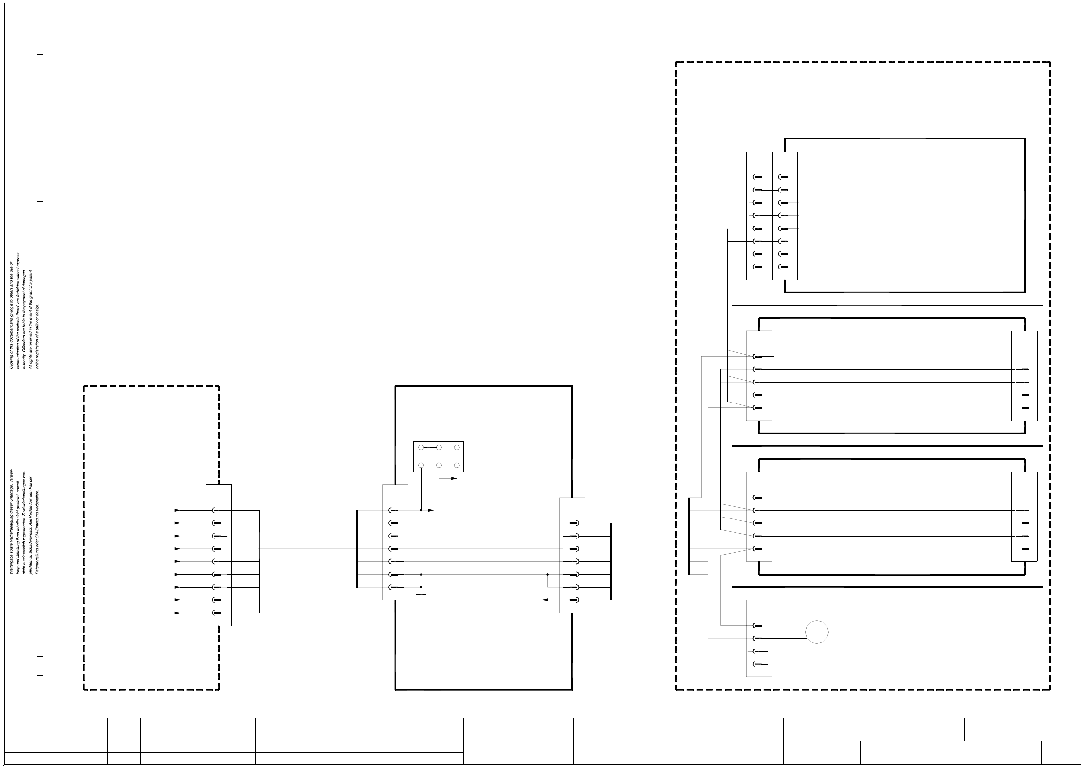
LP01-F5HM PCB conveyor 1 + 2, power supply
AenderungZustand Datum
CAD-Datei : LP1-F5HM.DWG
Urspr./Ers.f./Ers.d.NormName
Gepr.
Stromlaufplan/Circuit diagram
PL EA
Mat.-Nr. :
Beab. Hi
Datum 08.01.2001
SIEMENS
Sh.
Sh.
SMD Placement System SIPLACE F5 HM
1
1
PCB conveyor 1 + 2
Power supply
3
2
1
4
5
6
7
gn
br
wh
ye
gr
pk
bl
X1
7
4
6
5
3
2
1
+24VDC
30V switched
30V unswitched
70V switched
+5VDC
+24VDC
GND
00325581-xx
Conversion board
’dual conveyor’
6
GND
7
5
4
+5V
5
Not used
Key
Not used
Not used
4
3
2
1
6
7
8
GND
30V switched
Key
X2
X5c
wh
pk
gn
wh
br
gn
ye
gr
pk
bl
4
1
2
3
gn
ye
br
gr
X5a
2
5
4
3
1
Spare
70V switched
30V switched
30V unswitched
GND
wh
br
ye
pk
gn
2
5
4
3
X5b
GND
30V unswitched
30V switched
70V switched
Spare
1
X5d
gr
bl
23a
23b
22a
22b
21a
21b
J1
X25/27/29/31/33/35/37/39/
41/43/45/47/49/51/53/55/57
(Conveyor 2)
GND
3
2
X14
1
bl
gr
pk
br
wh
ye
8
9
gn
+15VDC
GND
GND
+30VDC switched
+5VDC
+24VDC
+70VDC switched
+30VDC unswitched
00345821-xx
Servo unit
(Cable)
00326070-xx 00326063-xx
(Cable)
6-channel
Half-bridge board
00325460-xx
Backplane, lifting table, width adjustment
Fan unit E1
PCB conveyor 2 (Option) 00325580-xx
Backplane, lifting table, width adjustment
PCB conveyor 1 00325580-xx
Control unit - single conveyor 00331465-xx
Control unit - dual conveyor 00327615-xx
or
M
X2a
X2b
X1c
28a/c
22a/c
32a/c
26a/c
32a/c
22a/c
28a/c
26a/c
24a/c,
24a/c,
24a
24b
1 Detailed Circuit Diagrams 31
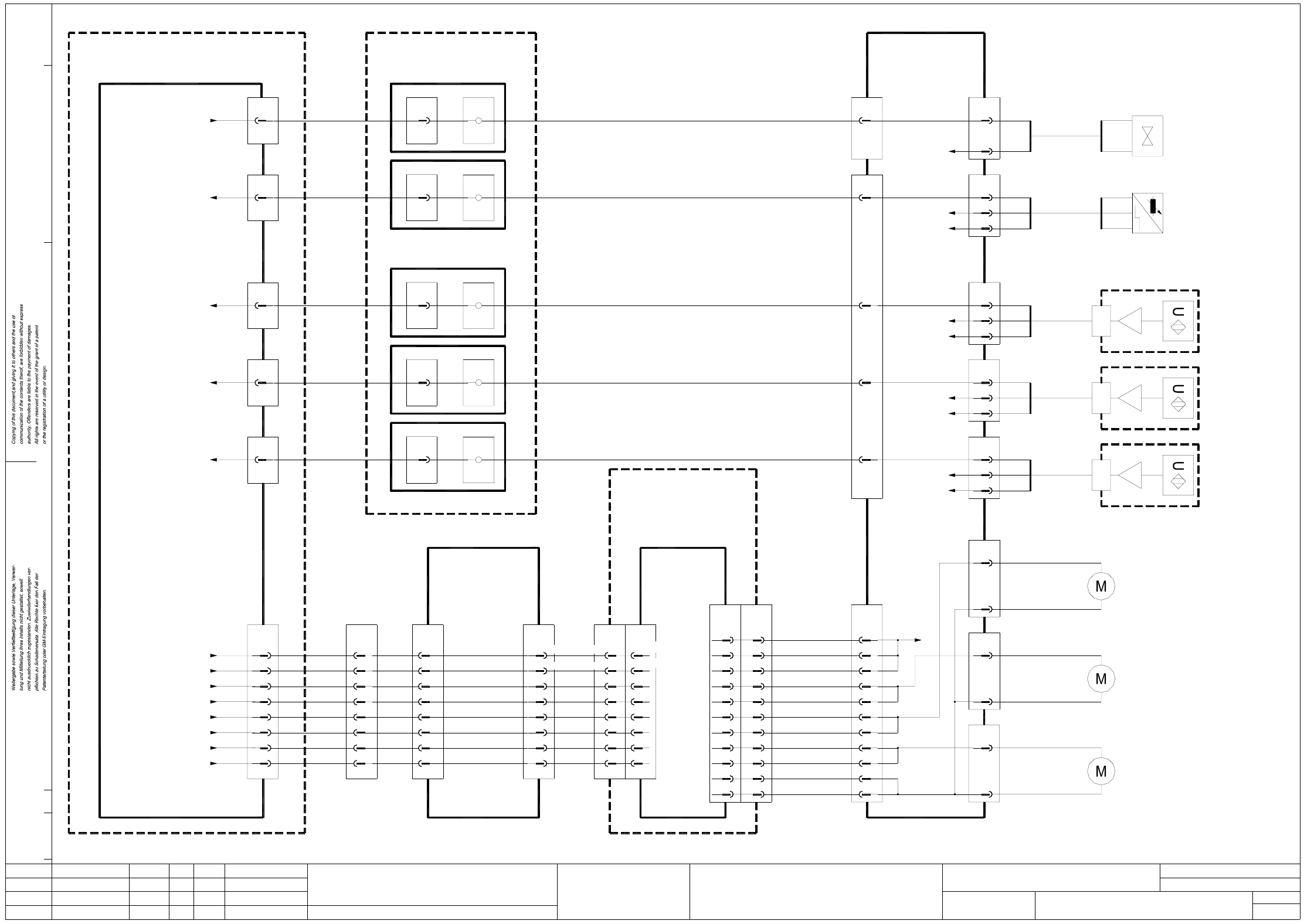
LP02-F5HM PCB conveyor 1, conveyor motors control
AenderungZustand Datum
CAD-Datei : LP2-F5HM.DWG
Urspr./Ers.f./Ers.d.NormName
Gepr.
Stromlaufplan/Circuit diagram
PL EA
Mat.-Nr. :
Beab. Hi
Datum 08.01.2001
SIEMENS
Sh.
Sh.
SMD Placement System SIPLACE F5 HM
1
1
PCB conveyor 1
Conveyor motors control
X1c
+30VDC switched
Center conveyor 1
X3’
29b
27a
28a
28b
27b
+24VDC
X40
3
2
bk
bl
GND
6
X42
2
(Cable)
00327655-xx
X34a
Sonar switch,
00326022-xx
input conveyor 1
00327656-xx
(Cable)
center conveyor 1
Sonar switch,
00326023-xx
X36a
00327657-xx
(Cable)
output conveyor 1
Sonar switch,
00326024-xx
X38a
br
bl -
+
bk A1
stopper 1
00326025-xx
Sensor switch,
+br
-wh
Valve,
00326026-xx
stopper 1
pk
6
X13
(Cable)
00326068-xx
pk
6
X12
12
8
10
rd-bl
rd
vio
Conversion board
’dual conveyor’
00325581-xx
7
X2ka
11
X2se
11
X1ka
00344228-xx
19
20
7 X1:4
GND
Output conveyor 1
29a
30b
32b
32a
30a
Input conveyor 1
GND
8
9
10
5
6
7
X2c
board
00325460-xx
X3
13,14
1,2,3,4
10
12
11
9
8
7
8
10
9
7
6
5
13,14,23,24
1,2,3,4,16,17,18
X6
+30VDC switched
GND
Center conv. 1 ’slow’
Center conv. 1 ’fast’
Output conv. 1 ’slow’
Output conv. 1 ’fast’
Input conv. 1 ’slow’
Input conv. 1 ’fast’
dual conveyor
00325581-xx
Conversion board
halfbridge
6-channel
(Cable)
00331297-xx00329283-xx
(Cable)
X1c
5a
4b
5b
4a
3a
3b
1a/b,2a/b,8a,9a/b
7b/a,12b/a
X4c
1
3
4
5
6
7
8
9
10
13
14
00327615-xx
dual conveyor
Control unit -
Control unit -
single conveyor
00331465-xx
(Cable)
A1
A1
(Cable)
00344230-xx
10
X4se
10
X1kb
7
X2kb
00326069-xx
(Cable)
A4
(Cable)
00344235-xx
11
X5sf
11
X2kg
7
X6kg
00326069-xx
(Cable)
A3
(Cable)
00344234-xx
11
X4sf
11
X1kf
7
X2kf
00326069-xx
(Cable)
A4
(Cable)
00344235-xx
9
X5sf
9
X2kg
5
X6kg
00326069-xx
(Cable)
9
11
10
7
8
13,14
1,2,3,4
12
1,2,3,4
13,14
9
8
7
12
11
10
Port A3.4
Port A3.5
Port A3.6
Port A3.7
I/O boards
Port A1.6
Port E1.5
Port E4.6
Port E3.6
Port E4.4
00344266-xx
Terminal panel, left-hand side
Valve ’Extend stopper 1’
Sensor switch ’Stopper 1 retracted’
Sonar switch ’output conveyor 1’
Sonar switch ’center conveyor 1’
Sonar switch ’input conveyor 1’
14
15
16
10
11
12
13
9
X7
26b
X2sf
Port A3.2
GND
+30VDC switched
Port A3.3
00345179-xx
Control unit
(Cable)
00345482-xx
00326067-xx
(Cable)
6
2
X18
-wh
+br
br
bk
bl
6
3
X34
2
-wh
+br
6
X20
2
-wh
+br
6
X22
2
output conveyor 1
00326030-xx
Conveyor motor,
Conveyor motor,
center conveyor 1
00326031-xx
Conveyor motor,
input conveyor 1
00326032-xx
GND
+24VDC
br
bk
bl
GND
6
+24VDC
X36
3
2
br
bk
bl
GND
6
+24VDC
X38
3
2
br
bk
bl
GND
6