F5HM Circuit Diagrams.pdf - 第147页
5 Pneumatic Diagrams 147 0032864 7-010201 XD3 T ape cutte r , pneumaticall y operated 00328647-010 201XD3 Tape cutter, pneumati cally operat ed Siplace Valve 1 Valve 2 Compressed a ir supp ly of serv icing unit mach ine …
5 Pneumatic Diagrams 146
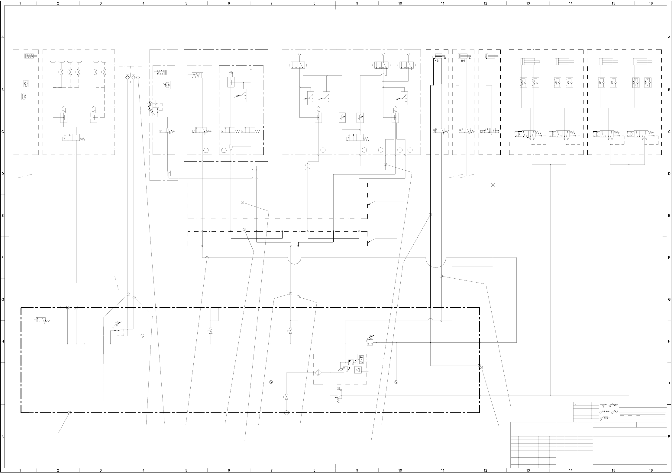
5 Pneumatic Diagrams
90000041-010103XD1 SIPLACE F* pneumatic diagram
B1
B2
B3
B4 B5 B6
B9
B7
B10
B11
B12
B13
p max. = 6 bar
B14
B15
B8
p = 2.0 + 0.2 bar
p = 2.0 +0.2 bar
p = 2.5 ± 0.2 bar
)(
NN ± N
mittel
1
A1
1710xxx Xxxxx xxx xx P
Tiefe:0,3/
2-5 um chemisch vernickelt
US 01 neu nn.nn.nn ----
US 02 Korr. Schl-lÌnge nn.nn.nn Schn
US 03 9462 Vacuum-Tool. 22.09.99 Schn
FSUAUSESFSStamm-Nr.
Freimasstoleranzen:
Genauigkeitsgrad
nach ISO 2768 mH
SIEMENS
PL EA
Zustand Mitteilung Datum Name
Freimassstoleranzen
<6
>6...30
>30...120
>120...400
>400...1000
±0,1
±0,2
±0,3
±0,5
±0,8
Oberfl.:
gehaertet HRc
einsatzgehaertet
NameDatum
Bearb.
Gepr.
Norm
Massstab
(Zeichnungsnummer)
Format
(Werkstoff,Halbzeug)
(Rohteil-Nr)
(Modell- oder Gesenk-Nr)
Hierzu gehoert
Koordinatenliste:
Sh.
Sheet
Copying of this document, and giving it to others and the use
or communication of the contents thereof, are forbidden with-
out express authority. Offenders are liable to the payment of
damages. All rights are reserved in the event of the grant of
a patent or the registration of a utility model or design.
Weitergabe sowie Vervielfaeltigung dieser Unterlage, Verwer-
tung und Mitteilung ihres Inhalts nicht gestattet, soweit nicht
ausdruecklich zugestanden. Zuwiderhandlungen verpflichten zu
Schadenersatz. Alle Rechte fuer den Fall der Patenterteilung
oder GM-Eintragung vorbehalten.
digital
8 bit
Nom. value
internal
external
p = 5.5 bar
36754
PU4/1500
90000041-010103XD1
p = 3.0 ± 0.2 bar
*) Nozzle closed!
Pneumatic system
SIPLACE F*
distributor
Gantry 2
Gantry 1
7 x hose 1
7 x hose 2
7 x hose 4
7 x hose 5
7 x hose 3
Trailing cable
7-fach-Schlauch-6
7 x hose 7
Gantry
Ø-nozzle 1mm
Placem.circuit
Ø-nozzle 1.5mm
Forced air
Holding circuit
Forced air
Pick&place head
Z-axis
clamping
Substrate
(Option)
centering
Vacuum tooling
(Option)
lh. side
rh. side
Table
Table
Z-axis
Connection for
feeder
(Option)
Bulk-Case-
Fluxing
vacuum generator
Pick&place head
Pick&place head
Reject
circuit
Collect&place head 6-12
Valve 2Valve 1 Valve 2 Valve 1
Ø 40 ; stroke 30
pneumatic
Tape cutterPCB stopperPCB stopper
(Option)
Nozzle
(Option)
changer
lefth. side
Cyl.1 Cyl.2
Ø 40 ; stroke 30
Cyl.1
Ø 40 ; stroke 30
Tape cutter
pneumatic
righth. side
Cyl.2
Ø 40 ; stroke 30
PU3/2800
PU3/2800
a
A
PR
b
Y1 Y1
b
RP
A
a
p = 2.5 ± 0.2 bar
p = 5.5 bar
Ø22/18 L=18
a
A
PR
b
YJ1
1
20.07.98 Schnellinger
E3
E2
E1
A1
A2
A4
A5
A3
A6
A7
PUN8/2400
PUN8/2400
PU3/2400
EZH-2,5/9-10
2219
8
3
7101112 13
14
6.9
(9)
PU4/1900
PU4/2800
a
A
PR
b
B16
5
1
4
3
2
ab
5
1
4
3
2
ab
5
1
4
3
2
ab
5
1
4
3
2
ab
PU4/1500
PU4/2600
PU4/100
Ø31/25 L=1,4
21
5.1 bar
PU3/2800
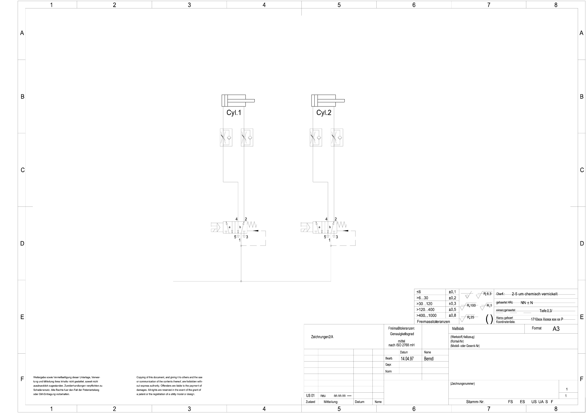
5 Pneumatic Diagrams 147
00328647-010201XD3 Tape cutter, pneumatically operated
00328647-010201XD3
Tape cutter, pneumatically operated
Siplace
Valve 1 Valve 2
Compressed air supply
of servicing unit
machine
Ø 40 ; Stroke 30 Ø 40 ; Stroke 30
Sheet
Sh.
AUT 5
SIEMENS
6 WPC 80F/3 148
6 WPC 80F/3
00319890-020101LD3 Overview
X12
X12 X13
X13
X8
X8X4
X4
Vertical axis Feed axis
TTM
Control unit / servo unit
Y201
X6 X3
X6 X3
X10X10 X9 X9
Y210-W22
M
M
Fan
X3
X3
X5
X5
X1
X1
X2
X2
Y203
Mounting plate
BY-X1
BY-X1
Y255-W33
Y255-W34
Y255-W35
Length of cables W1, W2 and
W3 0.80 m from cable clip
AY-X1
AY-X1
Y246-W8
Y244-W6
Y245-W7Y247-W31
Y247-W32
AM 61472. Heu13.3.97
to the middle of the plug.
Reference point, feed axis
Reference point, vertical axis
Limit switch, feed axis 1
Limit switch, feed axis 2
Limit switch, vertical axis top pos.
Limit switch, vertical axis bottom pos.
EMERG.-STOP
Y248-W10
Selector switch
Cover
Locking element against rotation, tray
Tray in magazine
Tray ready
Y203-W11
Y203-W12
Y251-W13
Y252-W14
Y253-W15
Y254-W16
Y203-W17
Y203-W18
Y203-W19
Y249-W20
Y250-W21
Y203-W23
Y203-W24
Crash light barrier, transmitter
Crash light barrier, received
B1002-W1
A1001-W1
Name Norm
Beab.
Urspr./Ers.f./Ers.d.
Sh.
Sh.Stromlaufplan/Circuit diagramDatumAenderungZustand
Datum
Gepr.
1816151413121110987654321 17
CAD-Datei :
Mat.-Nr. :
SIEMENS
AUT 5
1
1
00319890-020101LD3
01.09.1992
Heuberger F.
00319890-020101LD3
Overview
Waffle-Pack Changer 80F/3
SIPLACE
X7 X1
X1X2X7
X2 X1
Y241-W1
Y203-W4
Y243-W5
Y242-W2
Y242-W3
Infeed
EMERG.-STOP V24