F5HM Circuit Diagrams.pdf - 第9页
SIPLACE F5 HM Deta iled Circuit Diagra ms Folder 01/2001 U S Edition Table of Contents 9 : 3& ) 00319890 -020101L D3 Overview . . . . . . . . . . . . . . . . . . . . . . . . . . . . . . . . . . . . . . . . . …
SIPLACE F5 HM Detailed Circuit Diagrams Folder
01/2001 US Edition
Table of Contents 8
3QHXPDWLF'LDJUDPV
90000041-010103XD1 SIPLACE F* pneumatic diagram. . . . . . . . . . . . . . . . . . . . . . . . . . . . . . . . . . . . . . . . 146
00328647-010201XD3 Tape cutter, pneumatically operated. . . . . . . . . . . . . . . . . . . . . . . . . . . . . . . . . . . . . 147
SIPLACE F5 HM Detailed Circuit Diagrams Folder
01/2001 US Edition
Table of Contents 9
:3&)
00319890-020101LD3 Overview. . . . . . . . . . . . . . . . . . . . . . . . . . . . . . . . . . . . . . . . . . . . . . . . . . . . . . . . . . 148
00302827-020201LD3 Control unit / servo unit. . . . . . . . . . . . . . . . . . . . . . . . . . . . . . . . . . . . . . . . . . . . . . . 149
00302852-030101LD3 Control of servo boards and brake . . . . . . . . . . . . . . . . . . . . . . . . . . . . . . . . . . . . . . 150
00320064-030101LD3 Power supply (Sh. 1 of 4) . . . . . . . . . . . . . . . . . . . . . . . . . . . . . . . . . . . . . . . . . . . . . 151
00320064-030101LD3 EMERG.-STOP circuit (Sh. 2 of 4) . . . . . . . . . . . . . . . . . . . . . . . . . . . . . . . . . . . . . . 152
00320064-030101LD3 Mounting plate, distributor inputs (Sh. 3 of 4). . . . . . . . . . . . . . . . . . . . . . . . . . . . . . 153
00320064-030101LD3 Mounting plate, ground terminals (Sh. 4 of 4). . . . . . . . . . . . . . . . . . . . . . . . . . . . . . 154
00302827-020101ZD1 Control unit / servo unit. . . . . . . . . . . . . . . . . . . . . . . . . . . . . . . . . . . . . . . . . . . . . . . 155
00320064-030101MD1 Design of mounting plate . . . . . . . . . . . . . . . . . . . . . . . . . . . . . . . . . . . . . . . . . . . . . 156
SIPLACE F5 HM Detailed Circuit Diagram Folder
01/2001 US Edition
0 Drawing Numbering System 10
'UDZLQJ1XPEHULQJ6\VWHP
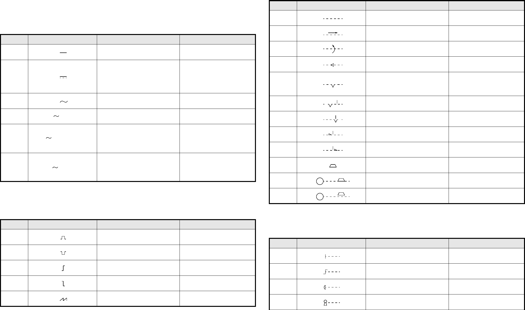
/HJHQGH6\PEROV
$UWHQYRQ6WU|PHQXQG6SDQQXQJHQ.LQGRIFXUUHQWDQGYROWDJH
,PSXOVIRUPHQ6LJQDOZDYHIRUPV
0HFKDQLVFKH6WHOOWHLOH0HFKDQLFDOFRQWUROV
$QWULHEVDUWHQ2SHUDWLQJGHYLFHVDQGPHWKRGV
1U1R 6FKDOW]HLFKHQ6\PERO %HVFKUHLEXQJ 'HVFULSWLRQ
02-02-01 Gleichstrom Direct current
02-02-03
Gleichstrom
$QPHUNXQJ
Das Schaltzeichen 02-02-03 muß ange-
wendet werden, wenn das Schaltzei-
chen 02-02-01 zu Verwechslungen
führt.
Direct current
1RWH
Symbol 02-02-03 is to be used if
symbol 02-02-01 causes confusion.
02-02-04 Wechselstrom Alternating current
02-02-05 Wechselstrom, 50 Hz Alternating current of 50 Hz
02-02-07
Dreiphasen-Vierleitersystem mit drei
Außenleitern und einem Neutralleiter,
50 Hz, 400 V (230 V zwischen jedem
Außenleiter und dem Neutralleiter).
3N darf durch 3/N ersetzt werden.
Alternating current: three-phase
with neutral, 50 Hz, 400 V (230 V
between phase and neutral).
3N may be replaced by 3 + N.
02-02-08
Dreiphasen-Fünfleitersystem mit drei
Außenleitern, einem Neutralleiter und
einem Schutzleiter, 50 Hz, direkte
Erdung eines Punktes, Neutral- und
Schutzleiter getrennt.
Alternating current, three-phase, 50
Hz: system having one point directly
earthed and separate neutral and
protective conductors throughout.
1U1R 6FKDOW]HLFKHQ6\PERO %HVFKUHLEXQJ 'HVFULSWLRQ
02-10-01 Positiver Impuls Positive-going pulse
02-10-02 Negativer Impuls Negative-going pulse
02-10-04 Positive Schrittfunktion Positive-going step function
02-10-05 Negative Schrittfunktion Negative-going step function
02-10-06
Sägezahn Saw-tooth
50 Hz
3N 50 Hz 400/230 V
3/N/PE 50 Hz / TN - S
1U1R 6FKDOW]HLFKHQ6\PERO %HVFKUHLEXQJ 'HVFULSWLRQ
02-12-01 Wirkverbindung, allgemein Mechanical connection (link)
02-12-02
Mechanische Verbindung mit Angabe
der Richtung von Kraft oder Bewegung
Mechanical connection with indica-
tion of direction of force or motion
02-12-03
Mechanische Verbindung mit Angabe
der Drehrichtung
Mechanical connection with indica-
tion of direction of rotation
02-12-07 Selbsttätiger Rückgang Automatic return
02-12-08
Raste
Nicht selbsttätiger Rückgang
Einrichtung zum Beibehalten einer
gegebenen Stellung
Detent
Non-automatic return
Device for maintaining a given posi-
tion
02-12-09 Raste, nicht eingerastet Detent, disengaged
02-12-10 Raste, eingerastet Detent, engaged
02-12-12 Sperre, nicht verklinkt Latching device, disengaged
02-12-13 Sperre, verklinkt Latching device, engaged
02-12-20 Bremse Brake
02-12-21 Elektromotor mit eingelegter Bremse Electric motor with brake applied
02-12-22 Elektromotor mit gelöster Bremse Electric motor with brake released
1U1R 6FKDOW]HLFKHQ6\PERO %HVFKUHLEXQJ 'HVFULSWLRQ
02-13-01 Handantrieb, allgemein
Manually operated control,
general symbol
02-13-04 Betätigung durch Drehen Operated by turning
02-13-08 Notschalter
Emergency switch (mushroom-head
safety feature)
02-13-13 Betätigung durch Schlüssel Operated by key
M
M