F5HM Circuit Diagrams.pdf - 第113页
4 Printed Circui t Boards 113 0032152 3-040202 ND4 IC-hea d board 0032152 4-040101 ND4 Sensor, z-axis, bottom 14.11. 96 TE Datum Name 14.11. 96 TE 18.03. 96 TE AUT-BSM 14.1 1.1996 TE - Ne X12 X10 X9 V8 C C B B C22 R14 R1…
4 Printed Circuit Boards 112
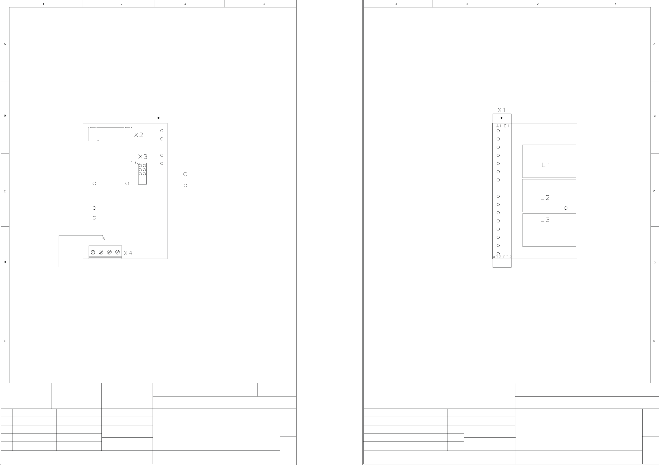
00321470-020202AD4 740 PCB, three-phase current for star axis (Sh. 1 of 2)
00321470-020202AD4 740 PCB, three-phase current for star axis (Sh. 2 of 2)
Function status
Product status
Doc. status
02
02
02
Zust. Mitteilung Datum
15.04.96 KD
Name
SIEMENS AG
FSZ MUENCHEN
Dorfner
24.07.95Datum
Name
00321470-020202AD4
G32918-F0040-B001-*-53
Three-phase current for star axis
740 printed circuit board
Component layout, component side
M 1:1
Sheet
1+
All documents viewed from the component side
Printed circuit board
ANL A441 TD FSZ E
15.04.96 KD
KD15.04.96
1) Pin 1 pinched offWire infeed
Component layout, solder side
Printed circuit board
M 1:1
740 printed circuit board
Three-phase current for star axis
G32918-F0040-B001-*-53
00321470-020202AD4
Sheet
2-
ANL A441 TD FSZ E
FSZ MUENCHEN
SIEMENS AG
Dorfner
24.07.95Datum
Name
KD
KD
KD
NameDatum
15.04.96
15.04.96
15.04.96
Function status
Product status
Doc. status
MitteilungZust.
02
02
02
4 Printed Circuit Boards 113
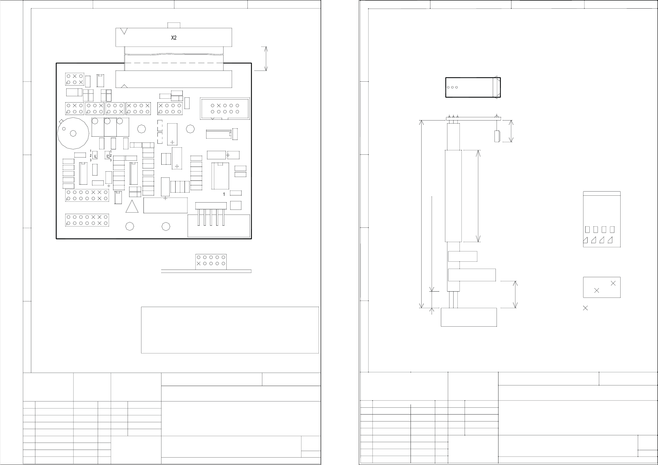
00321523-040202ND4 IC-head board
00321524-040101ND4 Sensor, z-axis, bottom
14.11.96 TE
Datum Name
14.11.96 TE
18.03.96 TE
AUT-BSM
14.11.1996
TE - Ne
X12
X10
X9
V8
CC
BB
C22
R14
R13
J6
R12
C18
AA
11
R24
R17
R16
R15
C24
C28
J7
C27
J1
C23
X11
The following labels have to be applied!
V6V5
Mount J6 on spacer
C: ESD label
A: Identification label
B: Inspection label
Maximum component height: 13 mm
Zust
2.
2.
4.
Aenderung
EE
DD
x = key
Datum
Bearb.
Gepr.
Norm
Siemens AG
R8
C29
P2
R9
R23
P1
R7
J2
C25
C
V2
V1
C1
R1
B
R4
C14
R3
R2
C6
C4
C3
C17
C13
C12
C16
C9
C8
C2
J3
X8
V12
J5
C11
V10
V11
V9
X6
22
00321523-040202ND4
Warning !!
Compare pressure sensor coding and solder connection (JP1,
JP2) with values RB25, RB125 in measurement values table:
RB25 < RB125: jumper 1-2
RB25 > RB125: jumper 2-3
IC head board
X3
Sheet
Sh.
X5
R6
X3
C7
A
C5
R5
L1
C15
J4
C10
V7
R26
X1
R25
C26
X4
33
±3mm
190mm
44
Function status
SMD Placement System Siplace 80S20
Doc. status
1
1
Product status
R21
R18
R10
C19
R11
C21
R19
C20
V4
R20
P3
V3
R22
X7
V1
3344
06.05.1996
Siemens AG
The following labels have to be stuck on!
Maximum component height: 7 mm
Solder cable from mounting side and do not bend.
V1
360 mm
Splice 25 mm
210mm
EE
DD
1.
Zust
1.
321524
Datum
06.05.96
06.05.96Prod. status
Doc. status
Aenderung
TE
TE
Name
Norm
Gepr.
Bearb.
Datum
TE - Ne
AUT-BSM
Mat.-Nr.:
X11
12783
KEY
KEY
B
A
CC
AA
BB
Silicone hose
TE
A: Identification label
B: Inspection label
1122
00321524-040101ND4
View onto cable side
= KEY
SMD Placement System Siplace 80S
/
20
Sensor z axis bottom
2:1
Massstab
20 mm
1
1
2
Sheet
1
1
Sh.
7
X11
X11
*
BAU
* : refer to 00321524-040101LD4
3. Funct. status 06.05.96 TE
4. Funct. status 01.04.98 bmk
4 Printed Circuit Boards 114
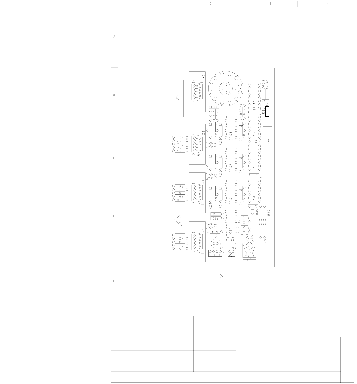
00322333-010304MD4 Video multiplexer, manually controlled
01 Datum
Name
11.10.95
KLOSE
SIEMENS AG
ANL A441 EPGM
Zeichnr.:
1710470-Y1025-000
M 1:1
Pinch off PIN
Video multiplexer
manually controlled
00322333-010304MD4
G32918-F0050-B001-*-17
1-
B = Inspection label
A = Identification label
C = ESD label
Sheet
Siplace 80S/F
Product status
Doc. status
Function status
Mitteilung Datum NameZust.
11.10.95
11.10.9502
02
KL
KL