F5HM Circuit Diagrams.pdf - 第75页
2 Circuit Diagr ams 75 0034582 1-010101 LD3 F5 HM servo unit (Gantry 1) 1 1 E D SMD Place ment System X-axis 34 C 5 Outp ut X2vc X1vg 3L+ A16 (vd ) Backplane (Gantry 1) Dynamic bra ke (Gantry 1 ) A4 A3 A11 Ballast circ u…
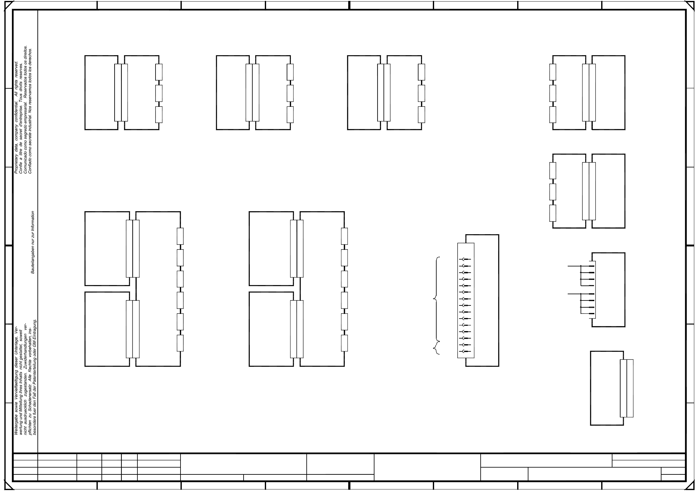
2 Circuit Diagrams 74
00342581-010102TD3 F5HM control unit, base (viewed from the back) (Sh. 2 of 2)
2
2
SMD-Placement System Siplace S23
Product status
Doc. status
Function status
Schadenersatz. Alle Rechte fuer den Fall der Patenterteilung
ausdruecklich zugestanden. Zuwiderhandlungen verpflichten zu
Weitergabe sowie Vervielfaeltigung dieser Unterlage, Verwer-
oder GM-Eintragung vorbehalten.
tung und Mitteilung ihres Inhalts nicht gestattet, soweit nicht
26.05.99
(viewed from the back)
A3
1:2
Massstab
02.
02.11.1998 Tekin
26.05.99
26.05.99
26.05.99
Tek
Tek
Tek
01.
01.
S23 control unit, basic module
00342581-020102TD3
Copying of this document, and giving it to others and the use
or communication of the contents thereof, are forbidden with-
out express authority. Offenders are liable to the payment of
damages. All rights are reserved in the event of the grant of
a patent or the registration of a utility model or design.
Blatt
Bl.
(Zeichnungsnummer)
Norm
Gepr.
Bearb.
Datum
Name
NameDatumMitteilungZustand
PL EA 1 E2
SIEMENS
Stamm-Nr.
Grounding point
Grounding point
SMP and AMS rear panels to be covered with 007 cover.
Power supply backplane A27
SMP bus A32
Fan unit Assembly A35 ( ue )
Vision system (ICOS2)
Video multiplexer A19
A18
Spare
Winchester/floppy
Axis board 1 x AC
Axis board
Axis board 1 x AC
Axis board
Comm. assembly
I/O board
Spare
I/O board
Machine controller
AMS bus A36
Assembly A30 (ud)
Assembly A29 (uc)
Assembly A27 (sz)
Assembly A28 (ta)
Machine controller GEM
Winchester/floppy GEM
Spare
I/O board
Spare
Spare
Edge protection
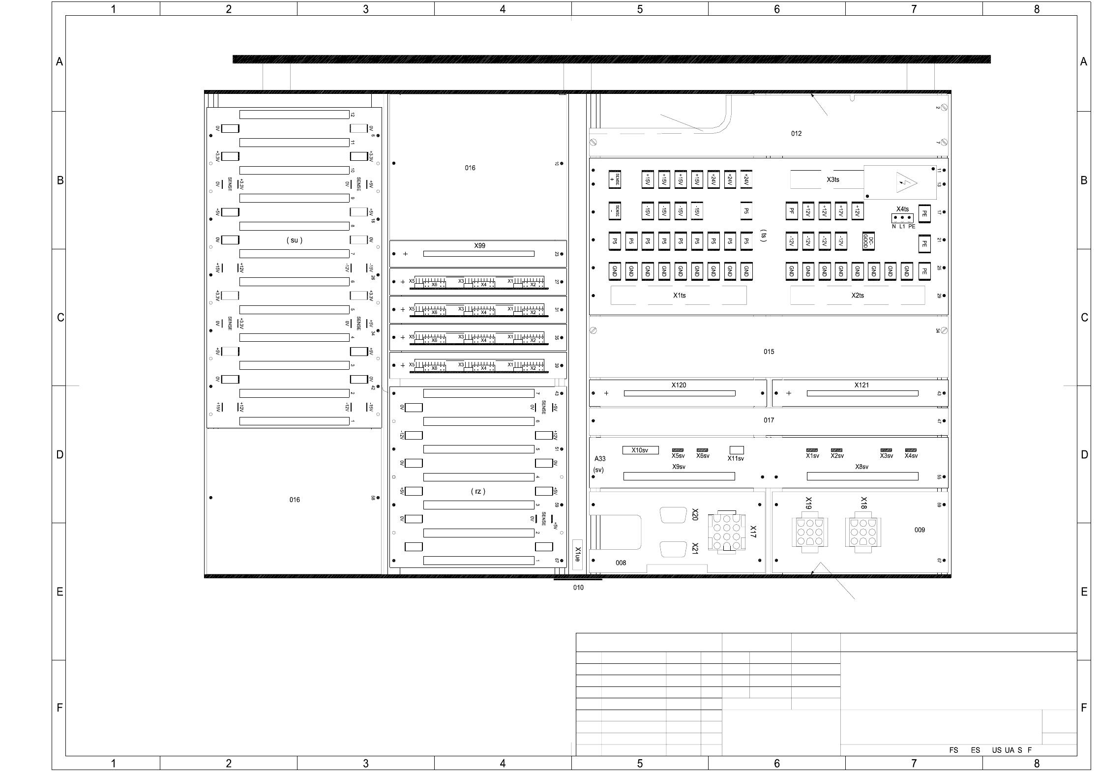
2 Circuit Diagrams 75
00345821-010101LD3 F5 HM servo unit
(Gantry 1)
1
1
E
D
SMD Placement System
X-axis
34
C
5
Output
X2vc
X1vg
3L+
A16 (vd)
Backplane
(Gantry 1)
Dynamic brake
(Gantry 1)
A4A3
A11
Ballast circuit
X-axis
Backplane
X4vf X3vf X2vf
6L+
SP head
X1
Servo amplifier
(Gantry 1)
Z-axis
SP head
X1
F
A17 (vc)
2L+/5L+
Star
X1
21
Servo amplifier
1L-
F
E
D
C
B
A
X3vcX4vc
SP head
X2vd
Servo amplifier
Motor
1L+/GND
Voltage +/-15V
Anti-crash board
Tachometer
X5va
3L+
X1
X1vf
Nom. values
X4va
X4vg X2vgX3vg
14
16
18
20
22
24
26
28
30
32
(+/-15V)
Power supply unit
Star
567
(Gantry 1)
A13 (va)
Backplane
(Gantry 1)
+15V
+15V
+15V
+15V
+15V
1L-
-15V
-15V
-15V
-15V
-15V
-15V
X1vk
Voltage
Tachometer
Motor
Nom. values
Z-axis
Backplane
X1
Servo amplifier
Z-axis
IC head
A9
A18 (vg)
IC head
DP1-axis
Backplane
(Gantry 1)
8
10
X6va
Voltage
Tachometer
Motor
Nom. values
X2va X1va
Input
X3va
A15 (vf)
X8va X7va
12
X6vbX7vbX8vb
X4vbX5vb
Y-axis
Servo amplifier
Y-axis
Dynamic brake
(Gantry 1)(Gantry 1)
+15V
X1vc
A8
Anti-crash board
Voltage +/-15V
1L+/GND
Motor
A14 (vb)
Backplane
(Gantry 1)
Y-axis
A7
A2
A19 (vk)
3L+
X4vk X2vkX3vk
Tachometer
Motor
Nom. values
DP1-axis
Servo amplifier
(Gantry 1)
678
123
X1
3L+
X12
4
6
c8
150V
Voltage
Tachometer
Motor
Nom. values
Voltage
Tachometer
Motor
Nom. values
A6
A1
X1vbX2vbX3vb
GND
c2
c4
c6
SIPLACE 80F5-HM
X3vdX4vd
X1vd
A5
A12
Anti-crash board
A10
X11
DP1-axis
Servo amplifier
X-axis
X4vaX5va
DP1-axis
Z-axis
Backplane
(Gantry 1)
8
A
B
4
Voltage
Deu
Deu
01
01
01
Function status
Product status
Document status
10.02.99
10.02.99
10.02.99
10.02.99
Tuth
#
F5-HM servo unit
00345821-010101LD3
X4vbX5vb
Tachometer
Nom. values
a2
a4
a6
a8
X13
PL EA1 E
Deu
=
Datum
Gepr.
Norm
Bearb.
Sheet
Urspr. Ers. f. Ers. d.NameDatumAenderungZustand
SIEMENS AG
Sh.
+
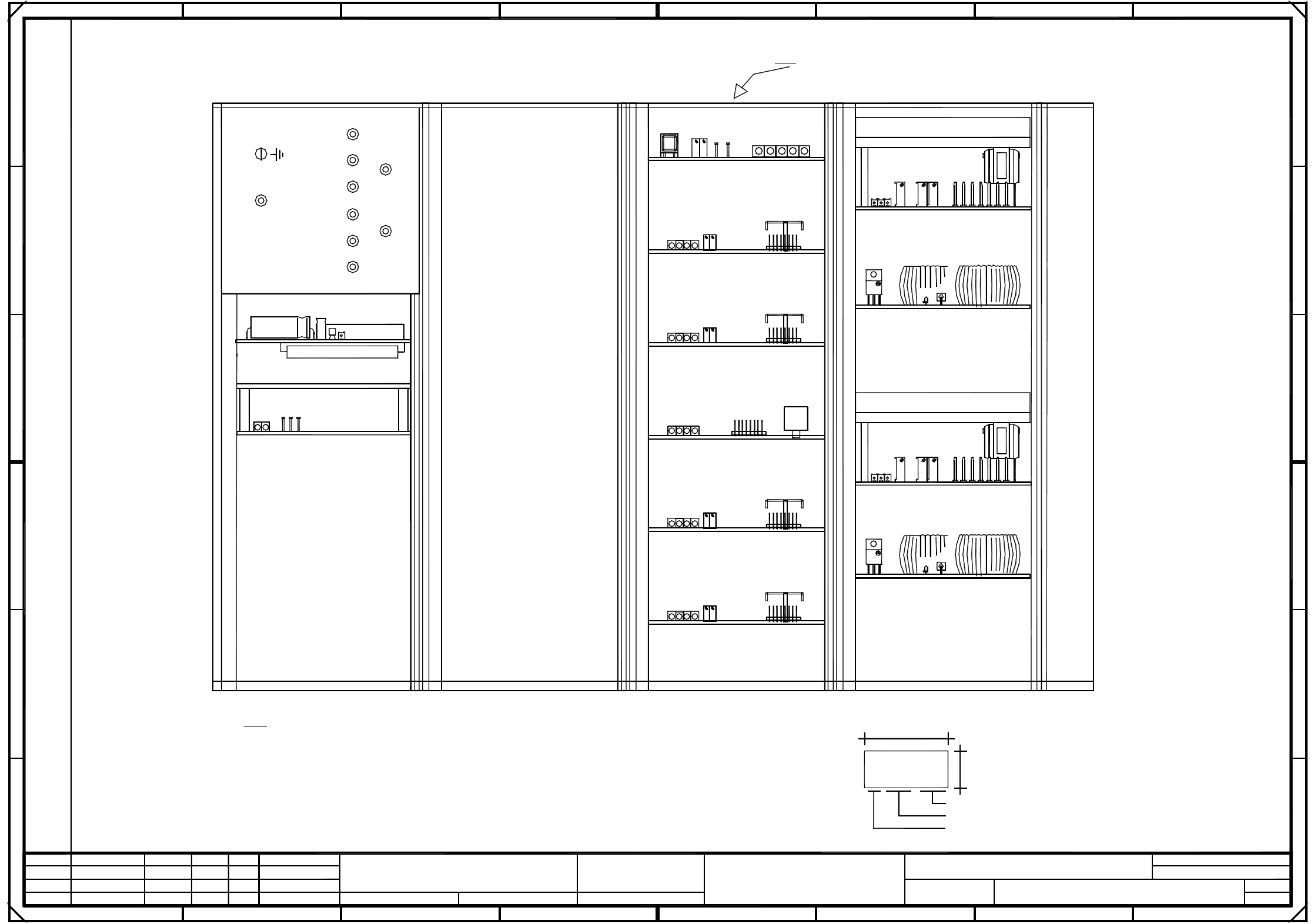
2 Circuit Diagrams 76
00345821-010101TD3 Servo unit (viewed from the front) (Sh. 1 of 2)
+
Sh.
SIEMENS AG
Zustand Aenderung Datum Name Ers. d.Ers. f.Urspr.
Sheet
Bearb.
Norm
Gepr.
Datum
=
Servo unit (viewed from the front)
PL EA1 E
81
SMD Placement System
2
Comunicado como segredo empresarial. Reservados todos os direitos.
Confie a titre de secret d’entreprise. Tous droits reserves.
Proprietary data, company confidential. All rights reserved.
"A7"
"A1"
00345821-010101TD3
#
Tuth
10.02.99
10.02.99
10.02.99
10.02.99
Document status
Product status
Function status
01
01
01
Deu
Deu
Deu
40
18
3
B
2
Ballast circuit "A11"
F
MJE
13005
6
13005
MJE
C
D
E
*Note:
Series number
A: Identification label Assembly inscription acc. to VA-F-510-001
Date (year/month/day) acc. to SN 01007
Manufacturer/location acc. to SN 37040
5V6L+
008
1L+
Anti-crash board "A10"
Fan unit A20
12V
005
009
004
nicht ausdruecklich zugestanden. Zuwiderhandlungen ver-
7
"A6"
DP1-axis
DP1-axis I "A15"
Z-axis
Z-axis I "A16"
Star axis
Star I "A17"
pflichten zu Schadenersatz. Alle Rechte vorbehalten, ins-
wertung und Mitteilung ihres Inhalts nicht gestattet, soweit
A
Weitergabe sowie Vervielfaeltigung dieser Unterlage, Ver-
006
Power supply unit "A12"
besondere fuer den Fall der Patenterteilung oder GM-Eintragung.
E
D
C
B
A
8765432
Apply the following labels on the outside
(flush with the front plate):
24V
00345821-xx
AA - BBBB - CCCC
SIEMENS PLEA1
DP1-axis, IC head
DP1-axis II "A18"
Z-axis, IC head
Z-axis II "A19"
SIPLACE 80F5-HM
F
003
B: Inspection label Identification:testing engineer, month, year
001
*Note
Power supply unit
Brake, Y-axis Y-axis
X-axis
Anti-crash board
Brake, X-axis
2L+
002
2L+/5L+
GND
007
7L+
Bauteilangaben nur zur Information
Confiado como secrete industrial. Nos reservamos todos los derechos.
1
45
Ballast
1
"A2"