F5HM Circuit Diagrams.pdf - 第52页
2 Circuit Diagr ams 52 001 17550-0 10201LD3 SIPLA CE F5 HM , basic mod ule (Sh. 6 of 6) 2 3456 78 12 3456 78 A B C D E F F E D C B A 21.04.99 18.10.99 SMD Placem ent System SIPLACE F5-HM 6 6 SIPLACE F5-HM basic module # …
2 Circuit Diagrams 51
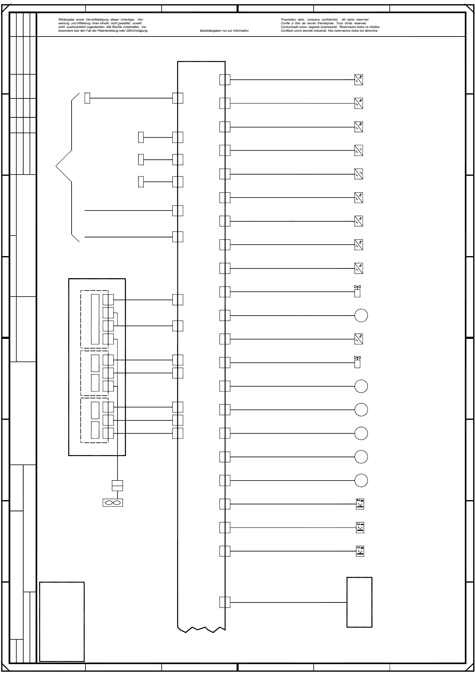
00117550-010201LD3 SIPLACE F5 HM, basic module (Sh. 5 of 6)
X46 X18 X20 X22 X16 X14 X50 X56X26 X28 X30 X32 X42 X44 X48
MMMMM
00326029-xx
X6 X7X1 X13
Conveyor control PCB 1
X46X26 X28 X30 X32
X1 X13
X14
X42 X44 X48 X18 X20 X22 X16 X14 X50 X56
X6 X7
00326027-xx
00326032-xx
00326031-xx
00326030-xx
00326033-xx
00326034-xx
00330944-xx
(Conveyor 1)Prox. switch,
adhesive wiper facility
(Conveyor 1)
(Conveyor 1)stopper
(Conveyor 1)
(Conveyor 1)
(Conveyor 1)
(Conveyor 1)
(Conveyor 1)
(Conveyor 1)
(Conveyor 1)
input conveyor
center conveyor
output conveyor
width adjustment
lifting table,
ceramic substrate centering
Motor,
Motor,
Motor,
Motor,
Motor,
Motor,
00326018-xx
00326019-xx
step motor, width narrower
Limit switch
Limit switch
(Conveyor 1)
(Conveyor 1)Light barrier, input conveyor
X52
X52
00330945-xx
(Conveyor 1)
Light barrier, center conveyor
X54
X54
00330946-xx
(Conveyor 1)Light barrier, output conveyor
Ceramic
substrate centering
00330950-xx
Special Bosch design (Conveyor 1)
Valve,
M
00326020-xx
00326021-xx
00326028-xx
ceramic substrate centering
=
Datum
Gepr.
Norm
Bearb.
Sheet
Urspr. Ers. f. Ers. d.NameDatumAenderungZustand
SIEMENS AG
Sh.
+
Prox. switch,
00326026-xx
Valve,
X40
X40
(Conveyor 1)
00326025-xx
stopper,Prox. switch,
X38
X38
00326024-xx
output conveyorSonar prox.switch,
(Conveyor 1)
X36
X36
00326023-xx
center conveyorSonar prox.switch,
(Conveyor 1)
X34
X34
00326022-xx
input conveyorSonar prox.switch, (Conveyor 1)
step motor, width wider
(Conveyor 1)
lifting table, bottom
(Conveyor 1)Prox. switch, lifting table, top
X24
X24
00326017-xx
(Conveyor 1)Prox. switch, lifting table, width
00326070-xx
X3
X3
00329283-xx
X3’
X4
X4
00329284-xx
X4’
X5
X5
00329285-xx
X5’
X12
Refer to
sheet 5
X12
00326069-xx
00326068-xx
00325581-xx
X2 X3
X2 X3
X4 X5
X4 X5
Half bridge
X1
00331297-xx
00326067-xx
X3 X4
X3 X4
X5
X5
Stroke/width 2
X2 X1
X8 X9
X8 X9
X3 X4
X3 X4
X5
X5
Stroke/width 1
X2
00326064-xx
00326061-xx
X1
X2
X2
00326063-xx
Step motor control
00327615-xx
X5d
X5d
Fan
X10
X10
00326065-xx
X11
X11
00326062-xx
5
6
SMD Placement System SIPLACE F5-HM
12345678
12345678
A
B
C
D
E
Deu
Tuth
Deu
01
01
Function status
Product status
Document status
21.04.99
18.10.99
21.04.99
18.10.99
Tuth
#
SIPLACE F5-HM basic module
00117550-010201LD3
FF
E
D
C
B
A
PL EA1 E5
01
02
PLEASE NOTE
This document will not
be replaced, when
modifications are made!
2 Circuit Diagrams 52
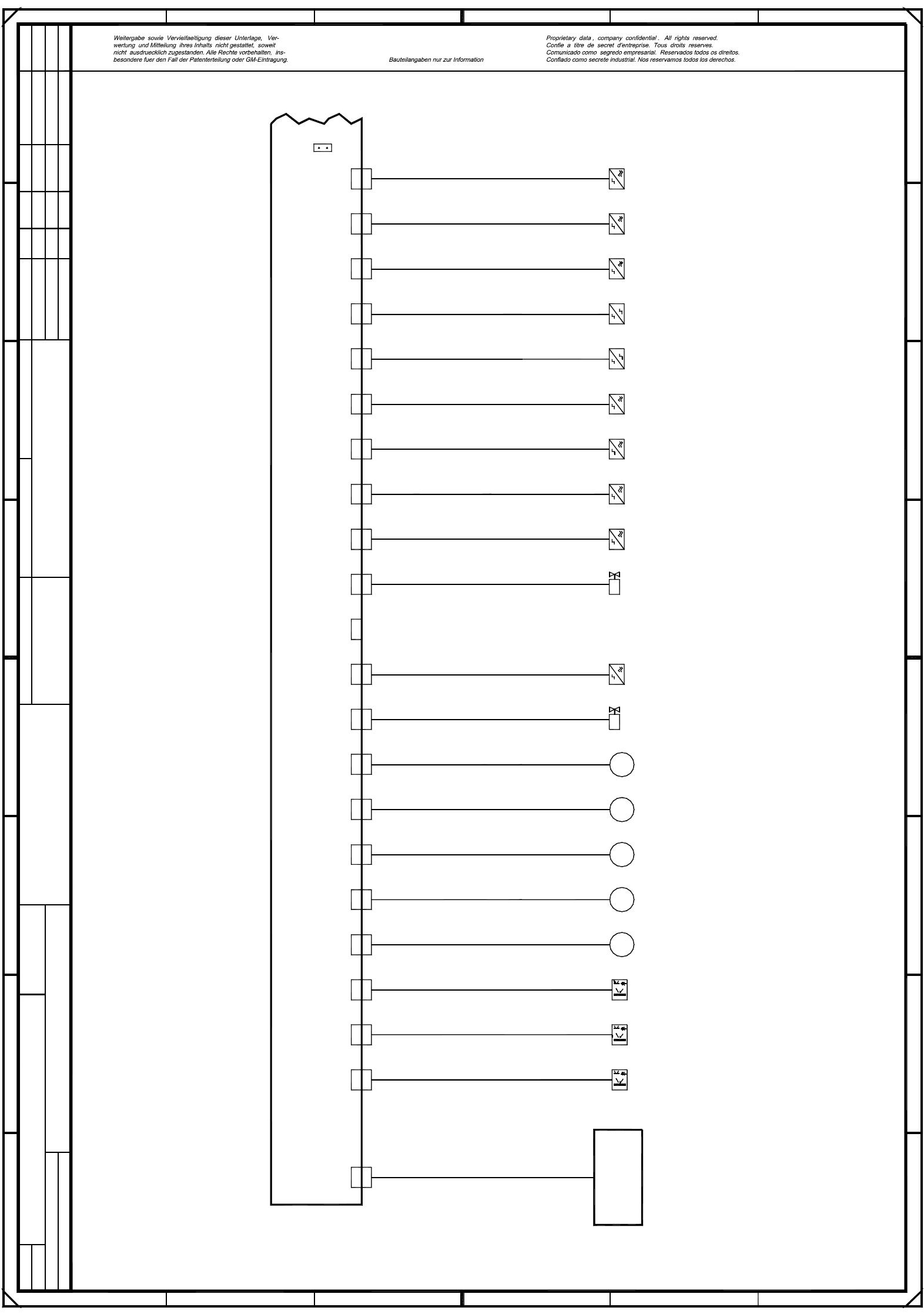
00117550-010201LD3 SIPLACE F5 HM, basic module (Sh. 6 of 6)
2345678
12345678
A
B
C
D
E
FF
E
D
C
B
A
21.04.99
18.10.99
SMD Placement System SIPLACE F5-HM
6
6
SIPLACE F5-HM basic module
#
Tuth
18.10.99
Document status
Function status
01
01
Deu
Tuth
Deu21.04.99
21.04.9921.04.99
1
MMMMM
00326051-xx
Conveyor control PCB 2
X47
X27 X29 X31 X33 X43 X45 X49X47 X19 X21 X23 X17 X15 X51 X57
00117550-010201LD3
00326052-xx
00326053-xx
00326054-xx
00326056-xx
00326058-xx
00330947-xx
(Conveyor 2)
(Conveyor 2)Prox. switch,
(Conveyor 2)
(Conveyor 2)stopper
(Conveyor 2)
(Conveyor 2)
(Conveyor 2)
(Conveyor 2)
(Conveyor 2)
X27 X29 X31 X33 X43 n. c. X49 X19 X21 X23 X17 X15
(Conveyor 2)
X51 X57
X55
X55
00330949-01
(Conveyor 2)
Light barrier, output conveyor,
Ceramic substrate
centering
00330951-01
Special Bosch design
(Conveyor 2)
Light barrier, input conveyor,
X53
(Conveyor 2)
X53
00330948-01
input conveyor,
center conveyor,
output conveyor,
width adjustment
lifting table,
ceramic substrate centering
Motor,
Motor,
Motor,
Motor,
Motor,
00326036-xx
00326037-xx
step motor, width narrower
Limit switch,
Limit switch,
lifting table, top
X25
00326043-xx
output conveyor,Sonar prox. switch, (Conveyor 2)
X37
X37
00326042-xx
center conveyor,Sonar prox. switch, (Conveyor 2)
X35
Valve,
00326038-xx
00326039-xx
00326049-xx
ceramic substrate centeringProx. switch,
00326045-xx
Valve,,
X41
X41
(Conveyor 2)
00326044-xx
stopperProx. switch,
X39
X39
(Conveyor 2)
Light barrier, center conveyor,
X25
00326035-xx
(Conveyor 2)Prox. switch,lifting table, width
00325581-xx
*X
* Insert jumper X
in machines
with dual conveyor option
X35
00326041-xx
input conveyor,Sonar prox. switch, (Conveyor 2)
step motor, width wider
(Conveyor 2)
lifting table, bottom
(Conveyor 2)Prox. switch,
02
01
PL EA1 E5PL EA1 E
01
02
Product status
=
Datum
Gepr.
Norm
Bearb.
Urspr. Ers. f. Ers. d.NameDatumAenderungZustand
SIEMENS AG
Sh.
+
=
Datum
Gepr.
Norm
Bearb.
Sheet
Urspr. Ers. f. Ers. d.NameDatumAenderungZustand
+
2 Circuit Diagrams 53
00117251-010101FD3 SIPLACE F5 HM, basic module, I/O assignment (Sh. 1 of 2)
X2se: 6
X2se: 5
X2se: 8
X2se: 7
Plug design.
A1/X2ka:6
A1/X2ka:7
A1/X2ka:8
A1/X2ka:M
A2/X2kc:2
A2/X2kc:1
A2/X2kc:P
X2se:11
X2se:10
X2se:12
X3se: 1-4
X3se: 6
X3se: 5
X2se:13-14
A2/X2kc:7
A2/X2kc:6
A2/X2kc:5
A2/X2kc:4
A2/X2kc:8
A2/X2kc:M
A1/X2kb:P
X3se: 8
X3se: 9
X3se:11
X3se:10
X3se:12
X4se: 1-4(*)
X3se:13-14
A2/X2kc:3X3se: 7
A1/X2ka:5X2se: 9
Input
Port E1.4
Port E1.6
Port E1.7
Port E1.5
Port E1.2
Port E1.3
Port E1.0
Port E1.1
Input
Port E2.4
Port E2.6
Port E2.5
Port E2.3
Port E2.2
Port E2.1
Port E2.0
GND
Limit switch, width adjustment, conveyor 1
Bero, stopper 1 retracted, conveyor 1
Bero, stopper 2 retracted, conveyor 2
Bero, position width adjustment, conveyor 1
Bero, lifting table bottom position, conveyor 1
Bero, lifting table top position, conveyor 1
Bero, ceramic substrate centering, conveyor 1
Contactor monitoring (software release)
+24VDC
Key-operated switch, 0 -> actuated
EMERG.-STOP button, 1 -> actuated
’Off’ button, 0 -> actuated
Control on, 1 -> K3/K4 on
Protective cover, 1 -> opened
’On’ button, 1 -> actuated
Compressed air sensor, 1 -> compressed air available
Port E2.7
GND
Control on, 1 -> K1/K2 on
A1/X2kb:1
A1/X2kb:2
A1/X2kb:3
A1/X2kb:4
A1/X2kb:6
A1/X2kb:7
A1/X2kb:8
A1/X2kb:M
A1/X2kb:5
X4se: 6
X4se: 5
X4se: 8
X4se: 7
X4se:10
X4se:12
X4se:11
X4se: 9
X4se:13-14
A2/X2kd:2
A2/X2kd:1
A2/X2kd:P
A2/X2kd:7
A2/X2kd:6
A2/X2kd:5
A2/X2kd:4
A2/X2kd:3
X5se: 6
X5se: 5
X5se: 8
X5se: 7
X5se:10
X5se:11
X5se: 9
X5se: 1-4(*)
A2/X2kd:8
A2/X2kd:M
X5se:12
X5se:13-14
Pins marked with an ’*’ are not hard-wired !
C
B
A
23
FF
E
D
67
45
1 67
B
C
D
E
8
12345
Tek
Tek
Tek
01.
01.
01.
17.07.98
17.07.98
17.07.98
17.07.1998
Tekin
00117251-010101FD3
8
A
1
2
SMD-Placement System SIPLACE 80 F5
Product status
Doc. status
Function status
I/O assignment
SIPLACE 80 F5, basic module
X5se:13-14
X5se:12
A2/X2kd:M
A2/X2kd:8
X5se: 1-4(*)
X5se: 9
X5se:11
X5se:10
X5se: 7
X5se: 8
X5se: 5
X5se: 6
A2/X2kd:3
A2/X2kd:4
A2/X2kd:5
A2/X2kd:6
A2/X2kd:7
A2/X2kd:P
A2/X2kd:1
A2/X2kd:2
X4se:13-14
X4se: 9
X4se:11
X4se:12
X4se:10
X4se: 7
X4se: 8
X4se: 5
X4se: 6
A1/X2kb:5
A1/X2kb:M
A1/X2kb:8
A1/X2kb:7
A1/X2kb:6
A1/X2kb:4
A1/X2kb:3
A1/X2kb:2
A1/X2kb:1
GND
+24VDC
GND
X2se: 9 A1/X2ka:5
X3se: 7 A2/X2kc:3
X3se:13-14
X4se: 1-4(*)
X3se:12
X3se:10
X3se:11
X3se: 9
X3se: 8
A1/X2kb:P
A2/X2kc:M
A2/X2kc:8
A2/X2kc:4
A2/X2kc:5
A2/X2kc:6
A2/X2kc:7
X2se:13-14
X3se: 5
X3se: 6
X3se: 1-4
X2se:12
X2se:10
X2se:11
A2/X2kc:P
A2/X2kc:1
A2/X2kc:2
A1/X2ka:M
A1/X2ka:8
A1/X2ka:7
A1/X2ka:6
X2se: 7
X2se: 8
X2se: 5
X2se: 6
X2se: 1-4
A1/X2ka:4
A1/X2ka:3
A1/X2ka:2
A1/X2ka:1
A1/X2ka:P
+24VDC
=
Datum
Gepr.
Norm
Bearb.
Blatt
Urspr. Ers. f. Ers. d.NameDatumAenderungZustand
SIEMENS AG
Bl.
+
PL EA1 E2
GND
MC1 (M44)
Icos MC1
+24VDC
GND
+24VDC
X5sf:13-14
X5sf:12
A4/X5kg:M
A4/X6kg:8
GND
X5sf: 1-4(*)
X5sf: 9
X5sf:11
X5sf:10
X5sf: 7
X5sf: 8
X5sf: 5
X5sf: 6
A4/X4kg:15
A4/X6kg:7
A4/X6kg:6
A4/X6kg:5
A4/X4kg:14
A4/X5kg:P
A4/X3kg:18
A4/X3kg:19
X4sf:13-14
X4sf: 9
X4sf:11
X4sf:12
X4sf:10
X4sf: 7
X4sf: 8
X4sf: 5
X4sf: 6
A3/X2kf:5
A3/X2kf:M
A3/X2kf:8
A3/X2kf:7
A3/X2kf:6
A3/X2kf:4
A3/X2kf:3
A3/X2kf:2
A3/X2kf:1
+24VDC
GND
X2sf: 9
A4/X4kg:19X3sf: 7
X3sf:13-14
X4sf: 1-4(*)
X3sf:12
X3sf:10
X3sf:11
X3sf: 9
X3sf: 8
A4/X5kg:M
A4/X5kg:8
A3/X2kf:P
A4/X5kg:7
A4/X5kg:6
A4/X5kg:5
A4/X4kg:18
X2sf:13-14
X3sf: 1-4
X3sf: 5
X3sf: 6
X2sf:12
X2sf:10
X2sf:11
A4/X5kg:G
A4/X3kg:14
A4/X3kg:15
+24VDC
GND
GND
X2sf: 1-4
X2sf: 7
X2sf: 8
X2sf: 5
X2sf: 6
Address
Port A3.2
Port A3.3
Port A3.1
Port A3.0
Port A3.7
Port A3.6
Port A3.5
Port A4.1
Port A4.0
Output
Port A4.7
Port A4.6
Port A4.5
Port A4.4
Port A4.3
Port A4.2
Output
Port A3.4
Signal designation
+30VDC switched
Motor, spare, on slow
Motor, spare, on fast
Conversion
board,
X2sf: 6
X2sf: 5
X2sf: 8
X2sf: 7
X2sf: 1-4
Plug design. I/O terminal
GND
+30VDC switched
GND
+24VDC
Motor, width adjustment wider, conveyor 1
Motor, width adjustment fast, conveyor 1
Component counter
A4/X3kg:15
A4/X3kg:14
A4/X5kg:G
X2sf:11
X2sf:10
X2sf:12
X3sf: 6
X3sf: 5
X3sf: 1-4
X2sf:13-14
A4/X4kg:18
A4/X5kg:5
A4/X5kg:6
A4/X5kg:7
A3/X2kf:P
A4/X5kg:8
A4/X5kg:M
X3sf: 8
X3sf: 9
X3sf:11
X3sf:10
X3sf:12
X4sf: 1-4(*)
X3sf:13-14
X3sf: 7 A4/X4kg:19
X2sf: 9
PCB handling
Motor, center conveyor on slow, conveyor 1
Motor, center conveyor on fast, conveyor 1
Motor, PCB input conveyor on fast, conveyor 1
Motor, output conveyor on fast, conveyor 1
Motor, output conveyor on slow 2, conveyor 1
Motor, output conveyor on slow 1, conveyor 1
’Received’ to previous station from conveyor 1
’Permission’ to previous station from conveyor 1
Motor, width adjustment narrower, conveyor 1
’Transferred’ to following station from conveyor 1
’Request’ to following station from conveyor 1
Input
Port E3.4
Port E3.6
Port E3.7
Port E3.5
Port E3.3
Port E3.2
Port E3.1
Port E3.0
Input
Port E4.4
Port E4.6
Port E4.5
Port E4.3
Port E4.2
Port E4.1
Port E4.0
Port E4.7
Distance sensor
Crash, portal 1
GND
Bero, nozzle changer SP, portal 2 opened
Bero, nozzle changer SP, portal 1 opened
Bero, nozzle changer SP, portal 1 closed
Bero, nozzle changer SP, portal 2 closed
+24VDC
A3/X2kf:1
A3/X2kf:2
A3/X2kf:3
A3/X2kf:4
A3/X2kf:6
A3/X2kf:7
A3/X2kf:8
A3/X2kf:M
A3/X2kf:5
X4sf: 6
X4sf: 5
X4sf: 8
X4sf: 7
X4sf:10
X4sf:12
X4sf:11
X4sf: 9
X4sf:13-14
A4/X3kg:19
A4/X3kg:18
A4/X5kg:P
A4/X4kg:14
A4/X6kg:5
A4/X6kg:6
A4/X6kg:7
A4/X4kg:15
X5sf: 6
X5sf: 5
X5sf: 8
X5sf: 7
X5sf:10
X5sf:11
X5sf: 9
X5sf: 1-4(*)
GND
A4/X6kg:8
A4/X5kg:M
X5sf:12
X5sf:13-14
Pins marked with an ’*’ are not hard-wired !
Ultrasonic sensor, input conveyor, conveyor 2
Ultrasonic sensor, input conveyor, conveyor 1
Ultrasonic sensor, output conveyor, transport 1
Ultrasonic sensor, output conveyor, transport 2
’Request’ to conveyor 1 from previous station
’Transferred’ to conveyor 1 from previous station
’Permission’ to conveyor 1 from following station
’Received’ to conveyor 1 from following station
Ultrasonic sensor, center conveyor, conveyor 2
Ultrasonic sensor, center conveyor, conveyor 1
Address
Port A1.2
Port A1.3
Port A1.0
Port A1.1
Signal designation
+24VDC
Retract lifting table, PCB release, conveyor 1
Extend lifting table, PCB clamping, conveyor 1
Valve, nozzle changer 2 opened
Valve, nozzle changer 1 opened
Port A1.7
Port A1.5
Port A1.6
Port A2.1
Port A2.0
Output
Port A2.7
Port A2.6
Port A2.5
Port A2.4
Port A2.3
Port A2.2
GND
+24VDC
Valve, ceramic substrate centering, conveyor 1
Valve, extend stopper 2, conveyor 2
Lamp, main fault indicator ready (green)
Valve, extend stopper 1, conveyor 1
Icos MC1
MC1 (M44)
GND
+24VDC
Software release, control on
Lamp, main fault indicator lefthand side (white)
Command ’read PCB barcode’ 2 (contactor relay)
Command ’read PCB barcode’ 1 (contactor relay)
Lamp, main fault indicator righthand side (white)
Output
Compressed air on/off Port A1.4
I/O terminal
A1/X2ka:P
A1/X2ka:1
A1/X2ka:2
A1/X2ka:3
A1/X2ka:4
X2se: 1-4