F5HM Circuit Diagrams.pdf - 第63页
2 Circuit Diagr ams 63 0033681 2-020102 TD3 Power suppl y structur e (Sh. 4 of 4) 70mm 28mm 85mm 40mm 003001 61-x x 1000m m 100mm 003429 17-x x C B A the di amete r of th e fixin g clamp sl ightly. spac er bol ts (le ngt…
2 Circuit Diagrams 62
00336812-020102TD3 Power supply structure (Sh. 3 of 4)
3
4
SMD-Placement System Siplace S23
Product status
Doc. status
Function status
transformer
L=110mm
304.0
678
123
1
678
E
B
ES 1 2 3 4 5 6 7 8 9 10
Typ 4AV1301-6CT
SIEMENS PLEA1
PLEA1 Serial No.: ...
D
C
B
Serial NO.
484848
105
SC
A
400
N
-
F F
E
D
C
A
0V42
105
24 230
T2
400
208208
140
PE
400
V1
45
-~
~~
+
400 208400
~
V5
A
10
~
248-5%150230
400
29.5
42
Three-phase transformer
42
+
-
120 +5%N
02
01
02
Deu
Leh
Leh
V4
~
+
~
08
=
Datum
Gepr.
Norm
Bearb.
Blatt
Urspr. Ers. f. Ers. d.NameDatumAenderungZustand
SIEMENS AG
Bl.
+
PL EA1 E
13.02.98
02.09.98
00336812-020102TD3
Power supply structure
#
Werner
04.12.98
04.12.98
V2
~
V3
~
-
A1
Single-phase
A: Identification label Assembly inscription acc. to VA-F-510-001 PL EA
B: Inspection label Test identification for products acc. to guideline VA-F-510-001
Apply the following labels:
Oval cable duct dia.=30mm L=100mm
Edge protection
current limiter
Cable duct dia.=20mm
2345
Inrush
T1
105
119.0
B
Mat.Nr.:00336812-01
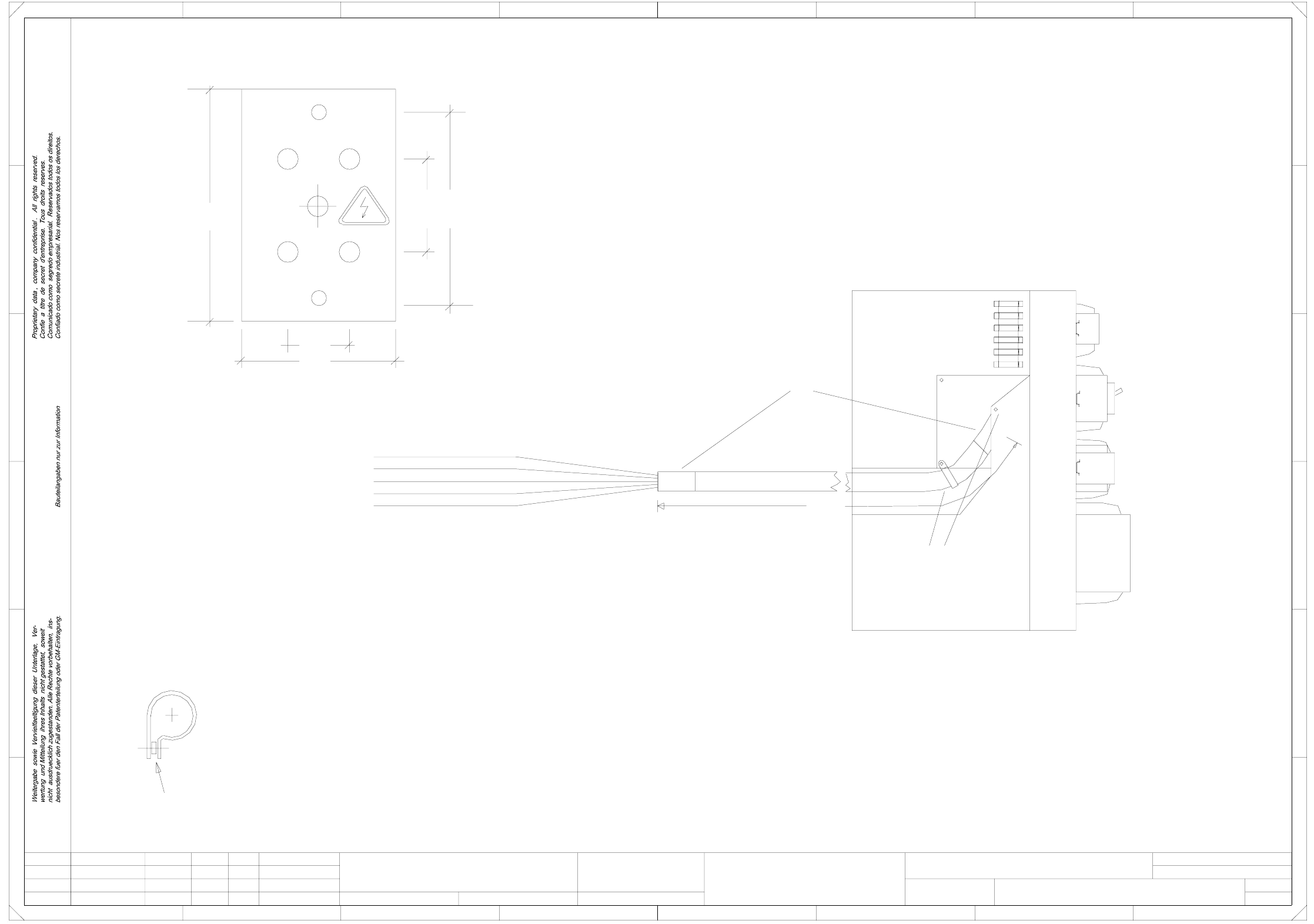
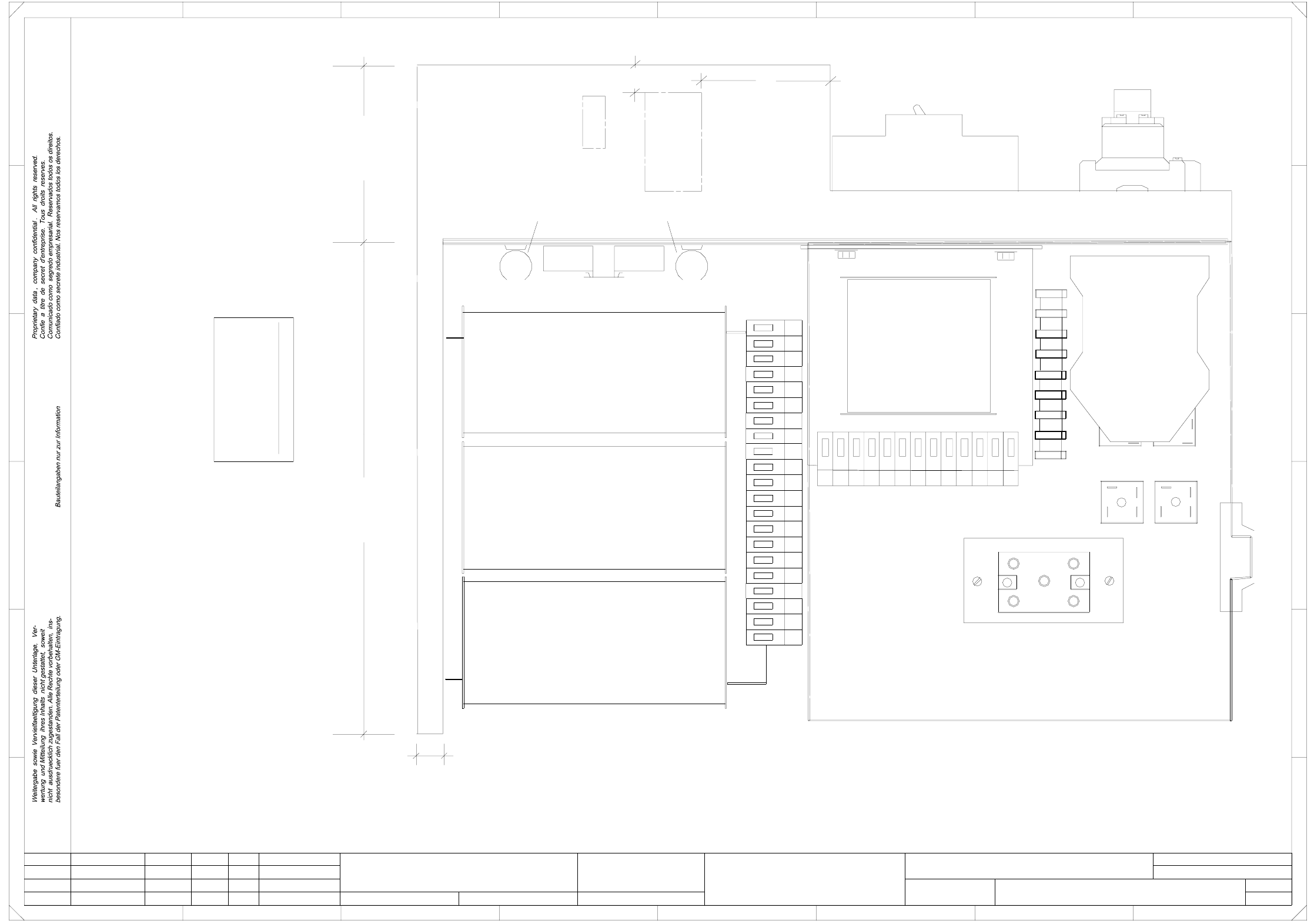
2 Circuit Diagrams 63
00336812-020102TD3 Power supply structure (Sh. 4 of 4)
70mm
28mm
85mm
40mm
00300161-xx
1000mm
100mm
00342917-xx
C
B
A
the diameter of the fixing clamp slightly.
spacer bolts (length: 50 mm) with M4 thread.
The cover vor bridge rectifier V1 is fixed using
Note !
3 spacing washer must be interposed in order to increase
Holes : symmetrical 2 x D= 4.5 mm
5 x D= 6 mm
Material: 1.5mm transparent macrolon
2345
8
12345678
A
B
C
D
E
FF
E
D
00324356-xx
Leh
Leh
Deu
02
01
02
02.09.98
23.01.98
04.12.98
Werner
#
Power supply structure
00336812-020102TD3
00324358-xx
00321113-xx
Round off corners and chamfer edges
1 67
4
4
SMD-Placement System Siplace S23
Product status
Doc. status
Function status
=
Datum
Gepr.
Norm
Bearb.
Blatt
Urspr. Ers. f. Ers. d.NameDatumAenderungZustand
SIEMENS AG
Bl.
+
PL EA1 E
04.12.98
Cover for bridge rectifier V1
2 x 10 cm heat-shrink sleeve
Flexible tubing
2 x fixing clamp
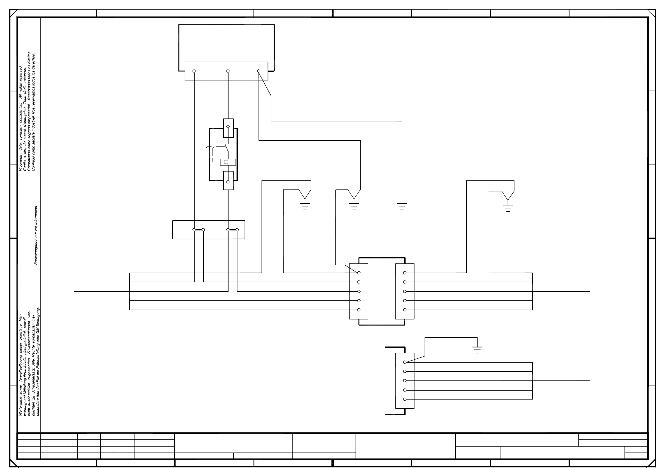
2 Circuit Diagrams 64
00300272-050101LD3 Service socket
bk
br
bk
00342917-01 (W2)
U profile
Service socket
78
A
B
C
filter
PE
L1
L3
E
D
Ground
machine
L3
N
L2
bk
bk
4
1
2
3
NLPE
N
Ground
main power plug
00342917-01
To
main switch
gnye
34
gnye
00342916-01 (W3)
frame
00342916-01 (W2)
gnye
1x2.5mm²
678
1
A1
bl
1x2.5mm²
00342916-01 (W5)
carrying bracket
gnye
gnye
gnye
1x2.5mm²
00342916-01 (W4)
Ground
(W1)
N
L2
X216
PE
L1
l=160mm
l=100mmbr l=100mm
1x2.5mm²
bk
br 1x2.5mm²
bk l=210mm
Ground
machine
frame
bl
A
1N1
2
l=350mm00342916-01 (W1)
To
1
F20
br
1
1
SMD Placement System SIPLACE 80S
bl
in
power supply
unit
12
23
C
B
D
E
FF
Main power
Z1
gnye
bk
gnye
5
456
(00321086-xx/00336812-xx)
S20/S2/F4
PE
L1
L3
N
L2
00321112-xx (W1)
To
main switch
gnye
sw
br
sw
bl
in
power supply
unit
(00315975-xx)
S15/F3/G2
Ground
machine
frame
00321112-xx (W2)
00300272-050101LD3
Service socket
#
Haas
20.07.98
17.07.98
17.07.98
17.07.98
Document status
Product status
Function status
01
01
t
Leh
Leh
Leh
PL EA1 E
=
Datum
Gepr.
Norm
Bearb.
Blatt
Urspr. Ers. f. Ers. d.NameDatumAenderungZustand
SIEMENS AG
Bl.
+