F5HM Circuit Diagrams.pdf - 第56页
2 Circuit Diagr ams 56 0033681 2-020101 FD3 Safety conce pt, overview, safety circ uit (Sh. 2 of 3) mach ine ON rele ase s ignal for (Input ) (ON bu tton) Key-op erated sw itch Safety circuit Emerg ency st op mus hroom -…
2 Circuit Diagrams 55
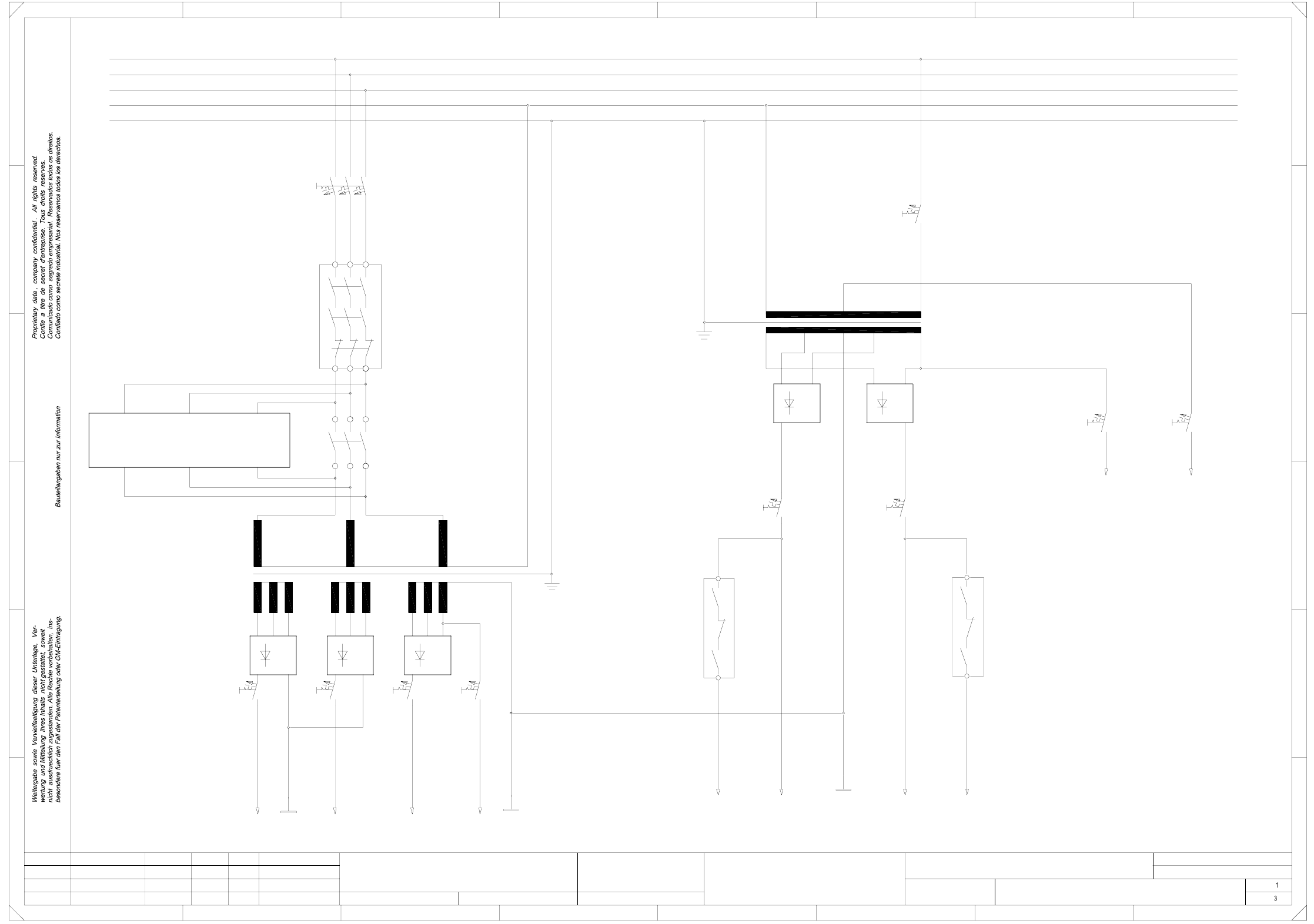
00336812-020101FD3 Circuit diagram overview, safety concept, power unit (Sh. 1 of 3)
SMD-Placement System Siplace S23
Product status
Doc. status
Function status
Safety concept (power unit)
L1
1L+
1L-
3L+2L+
4L+
V2
F7
T2
7L+
K1
L1
L2
L3
PE
N
5L+
K2
C
B
A
V4
13
K2
PE
L3
N
L2
2L-
V3
F6
V1
F9F8
F2
A1
T1
V5
14
23
FF
E
D
67
Switched
(Lifting table)
(dp1/Z axes)
(Star, slow)
(X,Y slow)
To
150VAC
safety circuit
24VAC
24VAC
(Tape cutter)
(Star/lifting table)
(X,Y axes)
45
1 67
B
C
D
E
8
12345
Leh
Leh
Leh
02
01
01
03.09.98
23.01.98
23.01.98
03.09.98
Werner
#
Circuit diagram overview
00336812-020101FD3
8
A
Switched
control unit
=
Datum
Gepr.
Norm
Bearb.
Blatt
Urspr. Ers. f. Ers. d.NameDatumAenderungZustand
SIEMENS AG
Bl.
+
PL EA1 E
To
Inrush
current limiter
(ext. WPC)
K4
F4 F5
6L+
2L-
F10 F11
F3
23
24
2 Circuit Diagrams 56
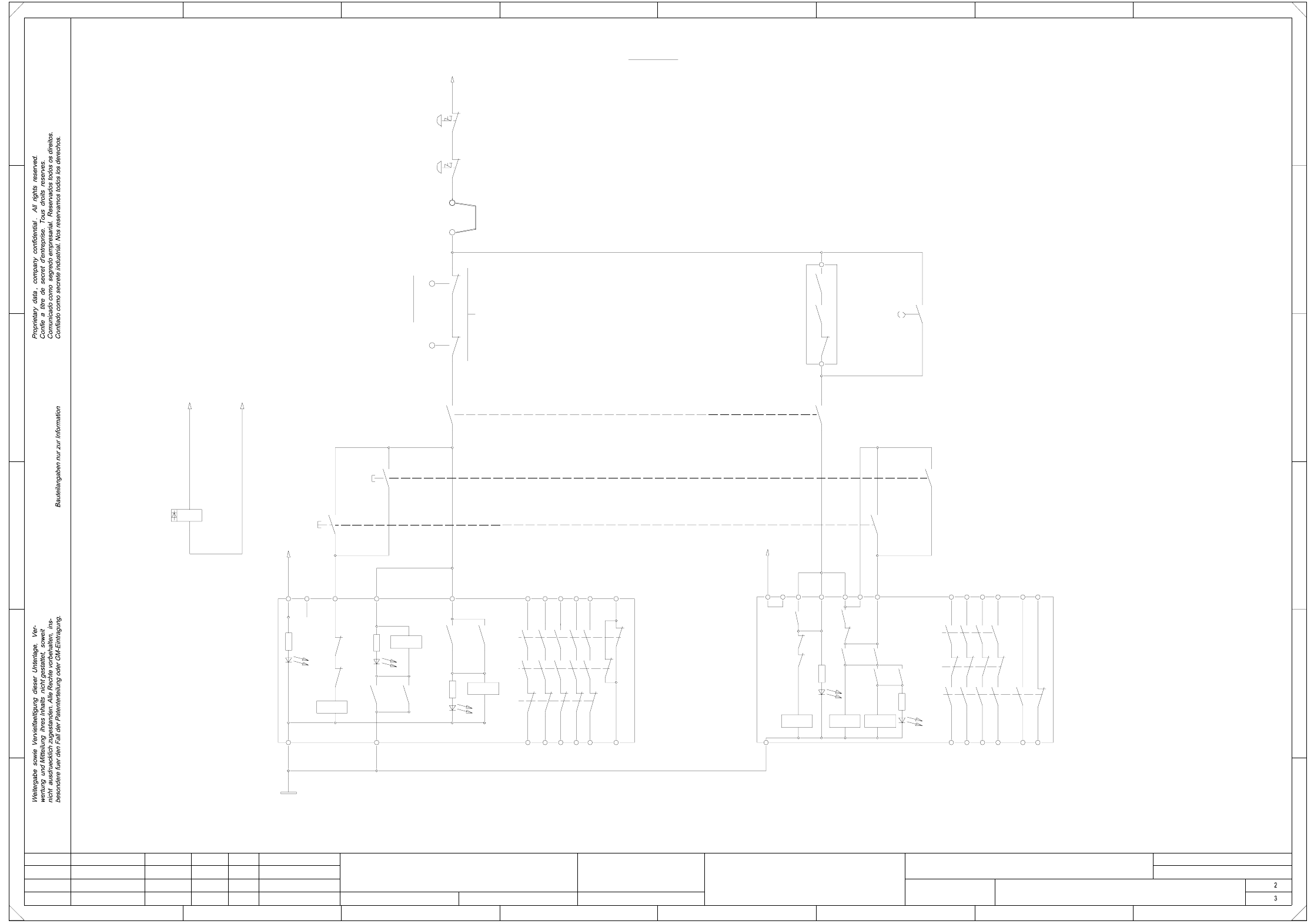
00336812-020101FD3 Safety concept, overview, safety circuit (Sh. 2 of 3)
machine ON
release signal for
(Input)
(ON button)
Key-operated switch
Safety circuit
Emergency stop mushroom-head push-button
(output)
Emergency stop mushroom-head push-button
5678
12
FF
E
D
C
B
A
(input)
safety loops
Connection for external
Cover switch
1234
13
X6
24V AC
24
14 34 44 58 66
L1
K2 3TK2804-0AC2
K3’
K2’
H2’
K3’
K1’ K3’
K1’
K2’
3323
K1 3TK2805-0AC2
K1’
K2’
H1
K3’
K2’K2’
K1’ K3’
L2
K1’ K2’
X1
(1-n)
Y0413-S1
X211
X211
Y0906-S1
Y0907-S1
~24VAC
H1’
3414 24
K1’
L1 X1
K1’
5743
44
E
78
A
B
C
D
K3’
K1’ K2’
H2
H3
K1’
K2’
13
X5
X3
24V AC
X6
L2
C0952-K3
Y0438-S1
K3’
65
Y0906-S2
Y0907-S2
C0952-K3
44
54
66
X4
K1’
K2’
K3’
X5
K3’
X3
43
54
53
Y0907-S4
K1
65
X2 X4
01
01
02
Leh
Leh
Leh
53433323
K1
PL EA1 E
00336812-020101FD3
Safety concept overview
#
Werner
03.09.98
23.01.98
23.01.98
03.09.98
SMD-Placement System Siplace S23
Product status
Doc. status
Function status
(Safety circuit)
=
Datum
Gepr.
Norm
Bearb.
Blatt
Urspr. Ers. f. Ers. d.NameDatumAenderungZustand
SIEMENS AG
Bl.
+
H2+H3 = Release signal
H3: LED, channel 1
H1: POWER LED H2: LED, channel 2
(Output)
Software
3456
H2’: LED Ready H1’: LED Release signal
2 Circuit Diagrams 57
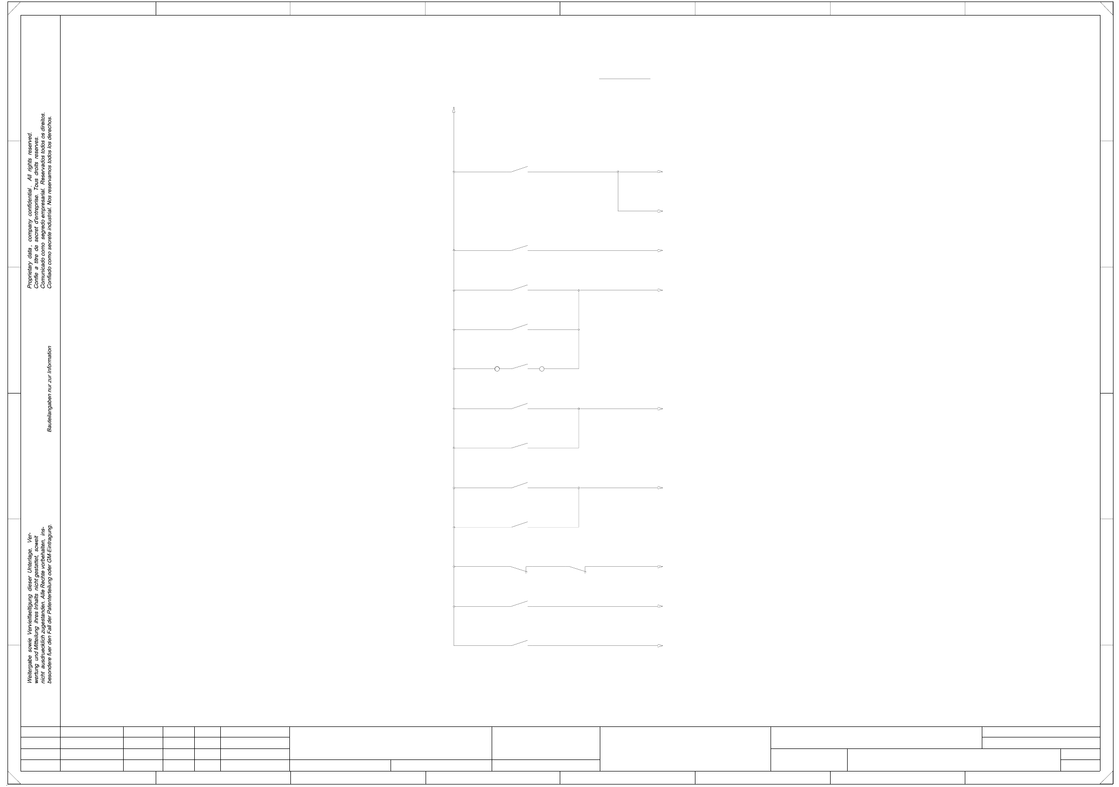
00336812-020101FD3 Safety concept, overview (signaling circuit) (Sh. 3 of 3)
3
3
SMD-Placement System Siplace S23
Product status
Doc. status
Function status
(Signaling circuit)
=
Datum
Gepr.
Norm
Bearb.
Blatt
Urspr. Ers. f. Ers. d.NameDatumAenderungZustand
SIEMENS AG
Bl.
+
5
4
Y0907-S3Y0906-S3
Y0907-S2
C0952-K1
K2
K1
Y0906-S2
Y0438-S1
X210
Y0907-S1
Y0906-S1
C0952-K2
C0952-K3
Y0907-S4
Y0413-S1
+24VDC
Monitoring
software release signal
Cover switch
Monitoring
Emergency stop mushroom-head push-button
Monitoring
Monitoring
(Siplace 80F)
Cover switch
(1-n)
Cover switch
External
Output
Input
Control ON
Control ON
123
234567
E
D
C
B
A
OFF button
Monitoring
Monitoring
ON button
Monitoring
key-operated switch
67
Laser
Monitoring
Signaling circuit
Software release signal
Key-operated switch
Input/Output
Output
Input
Leh
Leh
02
01
01
03.09.98
23.01.98
23.01.98
03.09.98
Werner
#
Safety concept overview
00336812-020101FD3
8
1 8
A
B
C
D
E
FF
PL EA1 E
Leh