F5HM Circuit Diagrams.pdf - 第19页
1 Detailed Circuit Diagr ams 19 X1-F5HM X-axis, gant ry 1, SIPLACE F5 HM 4 3 1 2 XT Tacho U Tacho V Tacho W Tacho Mp RSE U RSE V RSE W RSE +5V RSE GND U V W M 3~ 00337065-xx S-2 3 ye br gn ye/gn ye bk rd wh/bk rd vi wh/b…
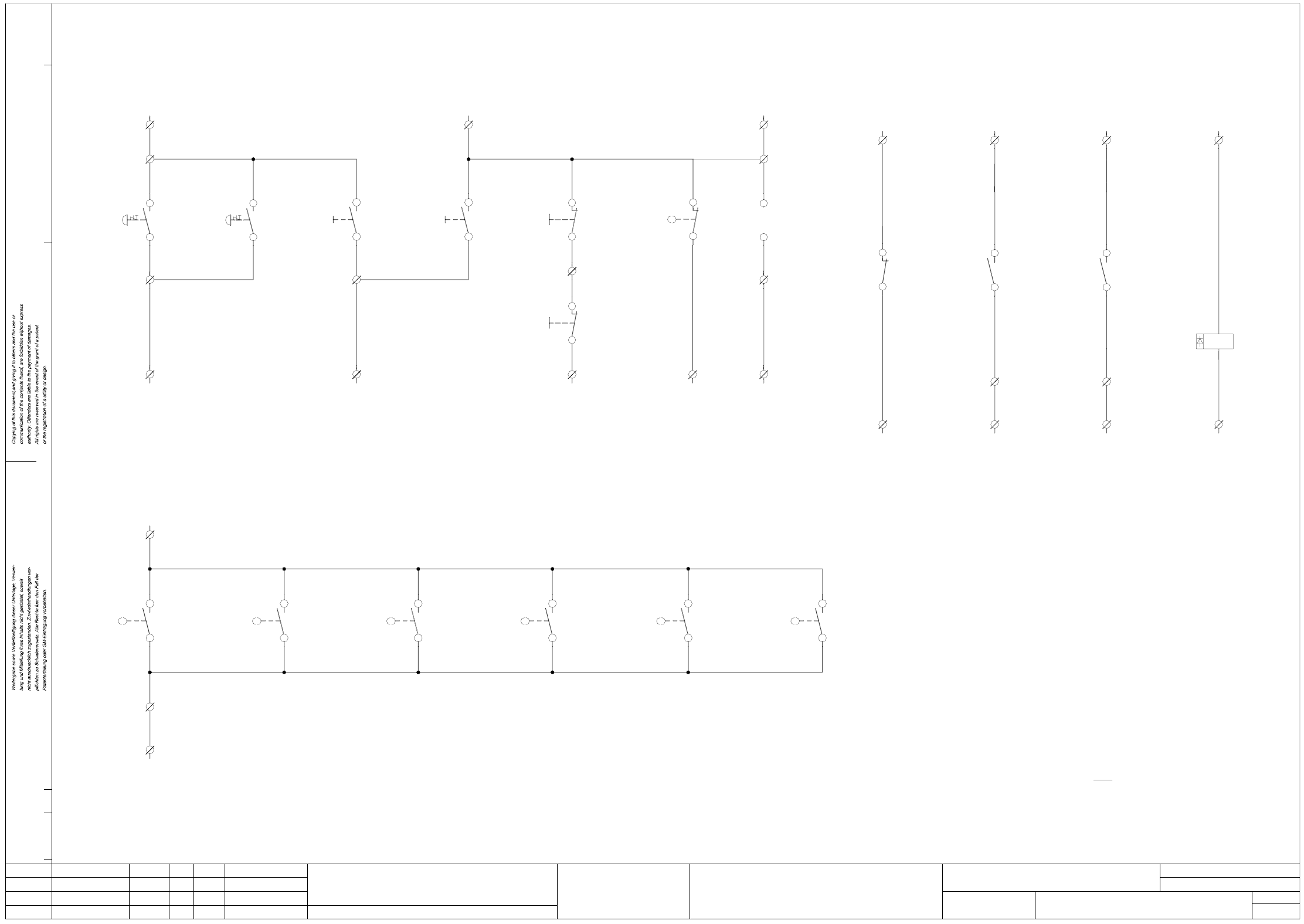
1 Detailed Circuit Diagrams 18
NOTF5HM2 Emerg.-stop circuit - signaling circuit, SIPLACE F5 HM
(S5 input) (S5 input)
1
2
(S5 input)
Key-operated
switch
00321529-xx S4
Push-button
(S5 input)
EMERG.-STOP EMERG.-STOP
X2KD + (+24VDC)
X2KC/M (S5 output)
X2KD/2
blbk
X210/1
6c
X210/2
5c
blbk
(S5 input)
EMERG. STOP
WPC interface, righthand side
00322112-xx pk
00322105-xx X57
00322112-xx gr
2KD + (+24VDC)
00322105-xx X57
SMD Placement System SIPLACE F5 HM
2
2
EMERG.-STOP circuit - signaling circuit
SIPLACE F5 HM
00344266-xx
Signaling circuit Signaling circuit Signaling circuit Signaling circuit
blbk blbk
monitoring of control ON and software release signal
Signaling circuits
Cover switch signaling circuit
EMERG.-STOP signaling circuits, ON/OFF push-buttons, key-operated switches
blbk
Cover open
X2KD/3 (S5 input)
machine
(Option)
00321421-xx S1 00321421-xx S1
(Option)
machine
Push-button Push-button Push-button
blbk
4
3
4
3
4
3
4
3
2
11
2
blbk blbk
Off button
00321432-xx vi
00321432-xx bk
Key-operated switch
00321434-xx bk
00321434-xx vi00321434-xx grpk
rdrd
00321434-xx rd
input conveyor
OFF
output conveyor
OFF
X2KD/6
X210/5
X2KD/5
00321528-xx S3
00321529-xx S3
X210/4
X2KD/4X2KD/2
X210/2
X210/1
X2KD + (+24VDC)
00321529-xx S200321528-xx S200321529-xx S100321528-xx S1
On buttonEMERG. STOP
00321433-xx ye 00321436-xx ye 00321432-xx grpk
00321432-xx rd00321436-xx gn00321433-xx gn
ONON
output conveyorinput conveyoroutput conveyor
push-button
input conveyor
push-button
X2KD+ (+24VDC)
X210/3
00321416-xx S1
00321417-xx S1 00321614-xx S1
14
1313
1414
13
00305818-xx wh
00305818-xx br
Cover protective
switch
output conveyor
00305817-xx br
00305817-xx wh
13
14
00303617-xx S1
13
14
00336812-xx K3
A2
A1
00336812-xx K1 00336812-xx K1
43
44
X211/21
X2KD/8 (S5 input)X2KD/1 (S5 input)
X211/22
58
57
+ 24VDC+ 24VDC
X2KB/7 (S5 input)
00336812-xx K3
22
21
+ 24VDC X2KC/8 (S5 output)
X212/4X212/4X212/4
K1
00321113-xx grbr00321113-xx whgn00321113-xx whye00321113-xx whye
00321113-xx brgn00321113-xx yebr00321113-xx whgr
Software release
Monitoring K2
Control OnControl On
Monitoring K3
Software release
X212 terminal strip (lefthand side)
X211 terminal strip (lefthand side)
X210 terminal strip (lefthand side)
Note:
13
14
Cover protective
lefthand side
switch
Cover protective
00321573-xx br
switch
righthand side
00321573-xx wh 00321574-xx wh
00321574-xx br
Cover protective
input conveyor
switch
preceding
switch
Cover protective
00305815-xx br
00305815-xx wh 00305816-xx wh
00305816-xx br
Cover protective
switch
succeeding
AenderungZustand Datum
CAD-Datei : NOTF5HM-2.DWG
Urspr./Ers.f./Ers.d.NormName
Gepr.
Stromlaufplan/Circuit diagram
PL EA
Mat.-Nr. :
Beab. Hi
Datum 08.01.2001
SIEMENS
Sh.
Sh.
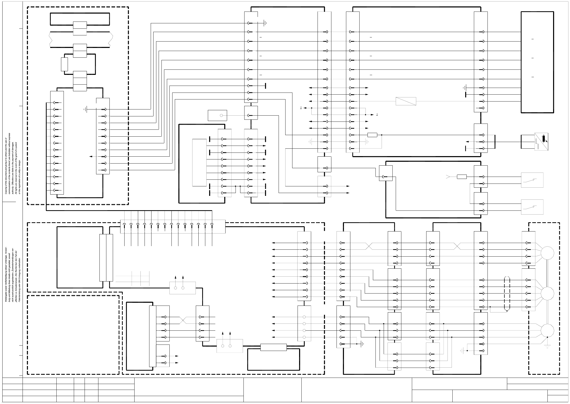
1 Detailed Circuit Diagrams 19
X1-F5HM X-axis, gantry 1, SIPLACE F5 HM
4
3
1
2
XT
Tacho U
Tacho V
Tacho W
Tacho Mp
RSE U
RSE V
RSE W
RSE +5V
RSE GND
U
V
W
M
3~
00337065-xx
S-23
ye
br
gn
ye/gn
ye
bk
rd
wh/bk
rd
vi
wh/br
or
X motor
(cable W2)
00337065-xx
(cable W1)
00337065-xx
prox. switch 1
End position
prox. switch 1
RSE = Rotary Shaft
Encoder
2
key
Track N
Track A
Track A
Track B
Track B
Track N
bl
wh
bk
gnwh
br
rd
vi
gn
ye
00349845-xx
29
(cable)
X2ab
large axis
wh
00322264-xx
(cable)
00346381-xx
00346382-xx
(cable)
A13 (va)
x axis (gantry 1)
+15V
-15V
2
1
X6va
X7va
1,2
3
-
0/155V
8
9
7
6
5
4
1
3
2
bl
br
ye
gr
rd
pk
gn
wh
(Gantry 1)
Axis
service
1,4,7,17,20
1,4,7,17,20
Screen
+5V
+15V
+5V
1,341,34
00321547-xx
(cable)
Anti-crash board
to X11e/6
to X11e/1
1
Switch
Gantry 1
Gantry 2
2
12
S2S1
X11e
6
1
4z Tacho Mp
Nom+
12b
12z
to X34aa
Conversion board
gantry
RLG W
Tacho W
RLG U
30d,z,b Motor V
32d,z,b Motor U
GND
+Ub
-15V
signal
4
3
2
1
8
7
10
bk
bl
Tacho U
Tacho V
Tacho W
Tacho Mp
RSE V
RSE W
RSE +5V
RSE GND
Motor U
Motor V
Motor W
Power GND
AenderungZustand Datum
CAD-Datei : X1-F5HM.DWG
Urspr./Ers.f./Ers.d.NormName
Gepr.
Stromlaufplan/Circuit diagram
PL EA
Mat.-Nr. :
Beab. Hi
Datum 08.01.2001
SIEMENS
Sh.
Sh.
SMD Placement System SIPLACE F5 HM
1
1
X axis
SIPLACE F5 HM
X1
00337333-xx A10
X5va
6
X35aa
2
00344266-xx
Terminal strip
X2kf
1
(cable)
00344224-xx
wh
(lefthand side)
gantry 1
Crash signal
00322262-xx
(cable)
00344206-xx A6 (va)
13,2813,28
+5V
11
12
11
12
X10aa
24
X2ab
24
bl3 bl -
X16ac
1
2
00300609-xx
br
bk bk
br
+
A1
End pos. prox.
switch B1
+24V
00336690-xx (aa)
Gantry
X8ab
3
1
wh
br
(Cable)
00321577-xx
Limit switch 1
x axis
00321423-xx
End pos. prox. switches
B1, B2
y axis
00321425-xx
Limit switch 2
x axis
00321578-xx
(Cable)
X9ab
3
1
wh
br
Conversion board
00345876-xx (ab)
large axis
S1 S2
conversion board
X38aa
2
6
1
8
7
(cable)
X10aa
29
30
00322262-xx
00345876-xx (ab)
Conversion board
2222
-15V
-15V
+15V
16
31
16
31
10
19
GND
+24V
10
19
GND
+24V
00354430-xx (ac)
Gantry head conversion board F5 HM
X34aa
1
Control unit
Power supply
00345179-xx
00334520-xx
+24V
00344217-xx
(cable)
+5V
+15V
-15V
9
8
7
6
5
+5V
-15V
+15V
+5V
+24V
X18
2
3
4
X12aa
1
+5V
00336690-xx (aa)
Gantry conversion board
Reference point
End position
X axis enable
Tacho U
Servo unit
00345821-xx
GND1
00345179-xx
Control unit
Cable 345488-xx
rd
nom. values
X axis
109
Axis rear panel, gantry 1 A27 (sz)
Ready out
8
GND
Enable3
2
Ready4
5I²t
6
7
14
12
13
10
11
12
13
11 Axis GND
Servo unit backplane
V nom9
10
Tacho-std12
GND
Force13
14
X2va
00344251-xx
(Cable)
X1su
X1sz
7
8
5
6
00345015-xx
3
4
1
2
8
9
5
6
2
3
X3su
X1sm
A6 (sm)
SMP bus A32 (su)
Axis board
X22
X7sz
X2sm
X3sm
X axis,
axis tracks
X1sa
GND
X1va
6
5
X8va
1
2
3
4
X3va
33
44
1
2
2
1
GND
Tacho-std
Ready
+15V
X11a
Anti-crash board
8b Enable input
Tacho std8d
Precontrol-14d
14b
Dynamic brake
DBM 120/3P
RSE
T
ye/gn
br
6
10
5
3
X-axis incremental shaft encoder
X15ac
9
1
7
4
8
GND
DGND
+5V
8
9
27
26 Track N
Track N27
26
X3ac
00322558-xx
6
5
2
3
29
30
33
32
X3aa
(Cable)
Track B
Track B29
30
Track A
Track A
33
32
X15aa
10
12
13
A
A
B
B
N
N
2525
X2sz
Machine controller M54 A1 (sa)
X1 plug assignment / servo amplifier
+15V
Tacho V
Brake out
Precontrol+
Nom-
10z
12d
10b
10d
8z
Pos. stop
Ready
Neg. stop
4b
4d
6b
2d
2b
Motor W
Power GND
18z
18b
28d,z,b
26d,z,b
20d,z,b
RLG V
GND
+15V
I²t
Force
16z
18d
16b
14z
16d
A1 (va)
00337625-xx
TBF 120 / 7 TS
X1
X-axis servo amplifier
X4va
RSE U
00343908-xx
3
4
5
10,11,12,13,14
X36aa
4
3
1
2
5
32
33
32
31
X37aa
29
30
33
X10aa
X11aa
30
32
33
X12ab
32
31
29
30
33
X2ab
3,6,9,12,15
4,7,10,13,16
2,5,8,11,14
3,6,9,12,15
4,7,10,13,16
X1ab
2,5,8,11,14
(cable)
00346191-xx
00322262-xx
(cable)
U
V
W
X13ab
4
3
2
1
10
8
7
6
5
X3ab
5
4
3
2
1
5
4
3
2
XR
1
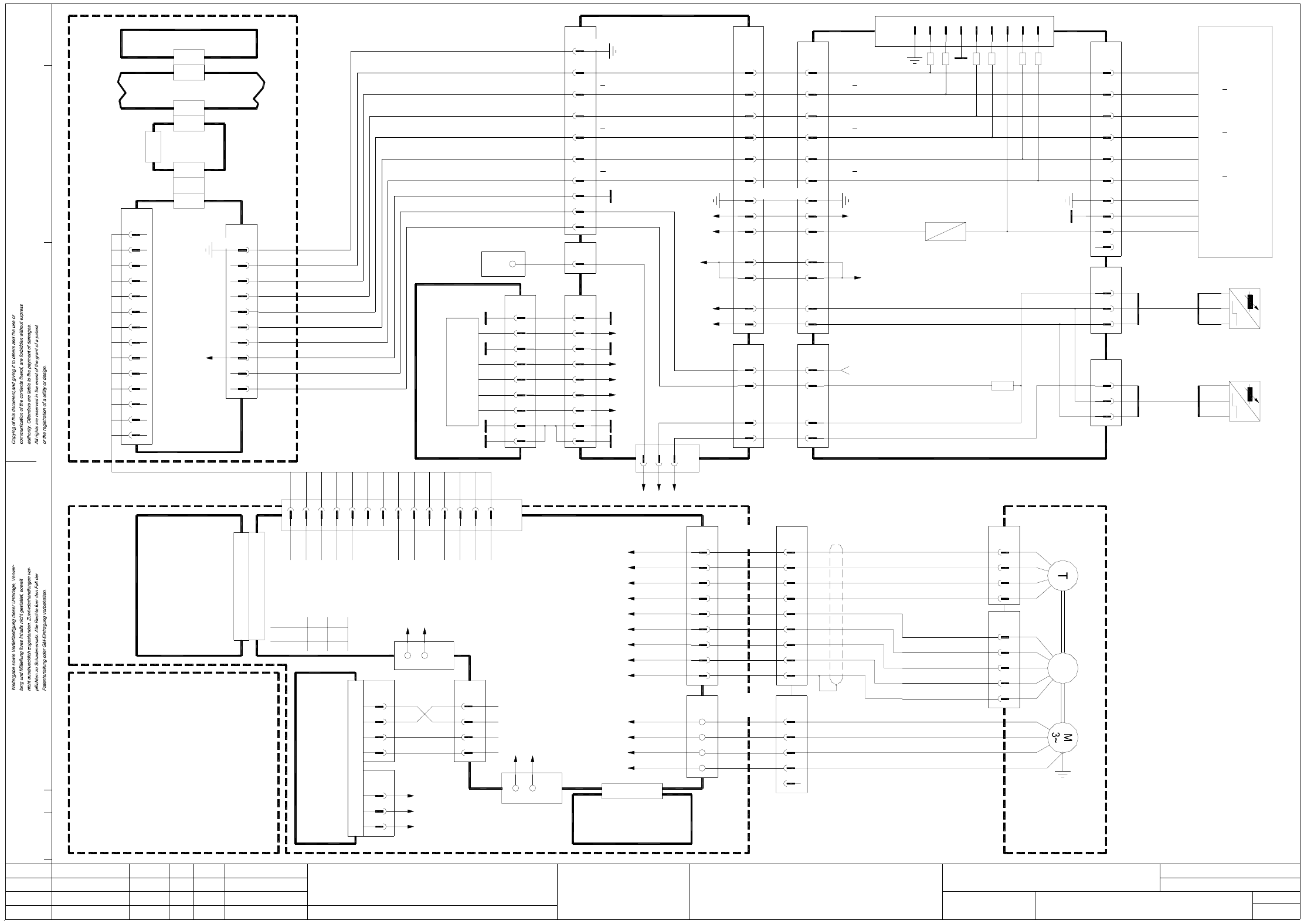
1 Detailed Circuit Diagrams 20
Y1-F5HM Y-axis, gantry 1, SIPLACE F5 HM
X4sz
Machine controller M54 A1 (sa)
00345179-xx
Control unit
Cable 00345490-xx
rd
nom. values
Y axis
109
Axis rear panel gantry 1 A27 (sz)
14
12
13
10
11
12
13
00344250-xx
(Cable)
X1su
X3sz
7
8
5
6
00345015-xx
3
4
1
2
8
9
5
6
2
3
X3su
X1sm
A6 (sm)
SMP bus A32 (su)
Axis board
X22
X7sz
X2sm
X3sm
Y axis
axis tracks
X1sa
GND
5
10
3
2
Y-axis incremental shaft encoder
X4ab
9
1
7
4
8
GND
DGND
+5V
8
9
27
26 Track N
Track N27
26
X1ab
00322264-xx
6
5
2
3
29
30
33
32
X11aa
(Cable)
Track B
Track B29
30
Track A
Track A
33
32
X23aa
10
12
13
A
A
B
B
N
N
15V
5V
-15V
2525
2222
AenderungZustand Datum
CAD-Datei : Y1-F5HM.DWG
Urspr./Ers.f./Ers.d.NormName
Gepr.
Stromlaufplan/Circuit diagram
PL EA
Mat.-Nr. :
Beab. Hi
Datum 08.01.2001
SIEMENS
Sh.
Sh.
SMD Placement System SIPLACE F5 HM
1
1
Y axis
SIPLACE F5 HM
TBF 120 / 12 TS
00337626-xx
Nom+
Tacho Mp
Neg. stop
Pos. stop
Nom-
4b
4z
4d
2b
2d
14b
14d
16d
14z
16b
Force
I²t
RLG V
signal
Tacho U
00345821-xx
Servo unit
A2 (va)
X1
00337333-xx A10
Anti-crash board
Ready33
Conversion board
X1
5
gantry
X11e
7
4
to X34aa
0/155V
+15V4
1,2
X7vb
-
3
X5vb
Gantry 1
Gantry 2
Switch
21
S1
1
S2
2
2
1
X11b
2
1
X6vb
-15V
+15V
X4vb
GND
Ready out
Enable
Ready
1
3
2
4
GND
I²t
Axis GND
V nom
8
5
6
7
9
10
11
Tacho-std
00343908-xx
Y axis (gantry 1)
A14 (vb)
Servo unit backplane
Tacho-std2
1GND
X3vb
Force
GND
13
12
14
X2vb
W3
6
Track A
Track A
Track B
Track B
Track N
Track N
1
X11ab
23456789
-15V
+15V
28
31
28
31
T
T
20
21
GND
+24V
20
21
GND
+24V
X5ab
5
3
1
X6ab
3
5
1
X2ab
27
26
24
23
X10aa
24
23
26
27
Limit switch
X axis loop
Conversion board
00345876-xx (ab)
large axis
bl
br
bk
bl
br
bk
bk
br
bl -
+
A1
bl -
A1
br +
bk
00300601-xx
00300905-xx
End pos. prox. switch B1
Y axis Y axis
End pos. prox. switch B2
X34aa
7
5
Control unit
Power supply
00345179-xx
00334520-xx
+24V
00344217-xx
(cable)
+5V
+15V
-15V
9
bl
wh
bk
gnwh
br
rd
vi
gn
ye
00349844-xx
key
br3
4
ye/gn 4
5
(cable W2)
00337066-xx
00346384-xx
X8vb
2
1
(cable)
bl
bk
RSE W 7
8
10
RSE U
RSE V
6
5
2
1
X31a
V
U
4
12
11
3
00346383-xx
X1vb
4
3
1
2
(cable)
10
2
X32a
1
9
rdV
Y motor F5
00337066-xx
W
ye/gn
ye
U
RSE GND
RSE +5V
RSE W
RSE V
RSE U
RSE
bk
vi
rd
2
4
XR
wh/br
wh/bk
or
5
3
1
Tacho Mp
Tacho W
Tacho V
Tacho U
XT
gn
br
wh
ye
4
3
1
2
to plug 11e
anti-crash board
6
13
00337066-xx
(cable W1)
(cable)
00321547-xx
Encoder
RSE = Rotary Shaft
Y axis
End position
prox. switch 1
prox. switch 2
End position
8
7
6
5
+5V
-15V
+15V
+5V
+24V
X18
2
3
4
X12aa
1
+5V
00336690-xx (aa)
Gantry conversion board
Reference point
End position
prox. switch 1
X aXis enable for Y
6
X35aa
2
00344266-xx
Terminal strip
X2kf
1
(cable)
00344224-xx
wh
(lefthand side)
gantry 1
Crash signal
00322262-xx
(cable)
1,17,18,19,34
1,4,7,17,20
1,4,7,17,20
(Gantry 1)
service
Axis
8
9
7
6
5
4
1
3
2
bl
rd
pk
gr
ye
wh
gn
br
Power GND
Motor W
Motor V
Motor U
RSE GND
RSE +5V
Tacho Mp
Tacho W
Tacho V
Tacho U
00344206-xx A7 (vb)
DBM 120/3P
Dynamic brake
Precontrol-
Power GND
X1 plug assignment / servo amplifier
RLG U
Tacho W
Precontrol+
12z
12b
12d
RLG W
Tacho std
Enable input
Ready
Brake out
Tacho V
+15V8z
10d
10b
10z
8b
8d
6b
28d,z,b
32d,z,b
30d,z,b
Motor U
Motor V
18d
16z
20d,z,b
26d,z,b
18b
18z GND
+Ub
Motor W
-15V
+15V
GND
Y axis servo amplifier