F5HM Circuit Diagrams.pdf - 第77页
2 Circuit Diagr ams 77 0034582 1-010101TD3 Assembli es overvie w (Sh. 2 o f 2) Anti-crash boar d Distan ce sensor -15V GND +15V 5 456 -15V Offs et Servo card, st ar axis, Tacho P gain Fault Ready stat us I r.m.s. li miti…
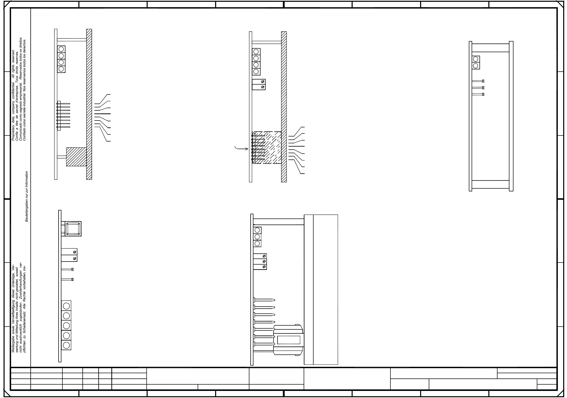
2 Circuit Diagrams 76
00345821-010101TD3 Servo unit (viewed from the front) (Sh. 1 of 2)
+
Sh.
SIEMENS AG
Zustand Aenderung Datum Name Ers. d.Ers. f.Urspr.
Sheet
Bearb.
Norm
Gepr.
Datum
=
Servo unit (viewed from the front)
PL EA1 E
81
SMD Placement System
2
Comunicado como segredo empresarial. Reservados todos os direitos.
Confie a titre de secret d’entreprise. Tous droits reserves.
Proprietary data, company confidential. All rights reserved.
"A7"
"A1"
00345821-010101TD3
#
Tuth
10.02.99
10.02.99
10.02.99
10.02.99
Document status
Product status
Function status
01
01
01
Deu
Deu
Deu
40
18
3
B
2
Ballast circuit "A11"
F
MJE
13005
6
13005
MJE
C
D
E
*Note:
Series number
A: Identification label Assembly inscription acc. to VA-F-510-001
Date (year/month/day) acc. to SN 01007
Manufacturer/location acc. to SN 37040
5V6L+
008
1L+
Anti-crash board "A10"
Fan unit A20
12V
005
009
004
nicht ausdruecklich zugestanden. Zuwiderhandlungen ver-
7
"A6"
DP1-axis
DP1-axis I "A15"
Z-axis
Z-axis I "A16"
Star axis
Star I "A17"
pflichten zu Schadenersatz. Alle Rechte vorbehalten, ins-
wertung und Mitteilung ihres Inhalts nicht gestattet, soweit
A
Weitergabe sowie Vervielfaeltigung dieser Unterlage, Ver-
006
Power supply unit "A12"
besondere fuer den Fall der Patenterteilung oder GM-Eintragung.
E
D
C
B
A
8765432
Apply the following labels on the outside
(flush with the front plate):
24V
00345821-xx
AA - BBBB - CCCC
SIEMENS PLEA1
DP1-axis, IC head
DP1-axis II "A18"
Z-axis, IC head
Z-axis II "A19"
SIPLACE 80F5-HM
F
003
B: Inspection label Identification:testing engineer, month, year
001
*Note
Power supply unit
Brake, Y-axis Y-axis
X-axis
Anti-crash board
Brake, X-axis
2L+
002
2L+/5L+
GND
007
7L+
Bauteilangaben nur zur Information
Confiado como secrete industrial. Nos reservamos todos los derechos.
1
45
Ballast
1
"A2"
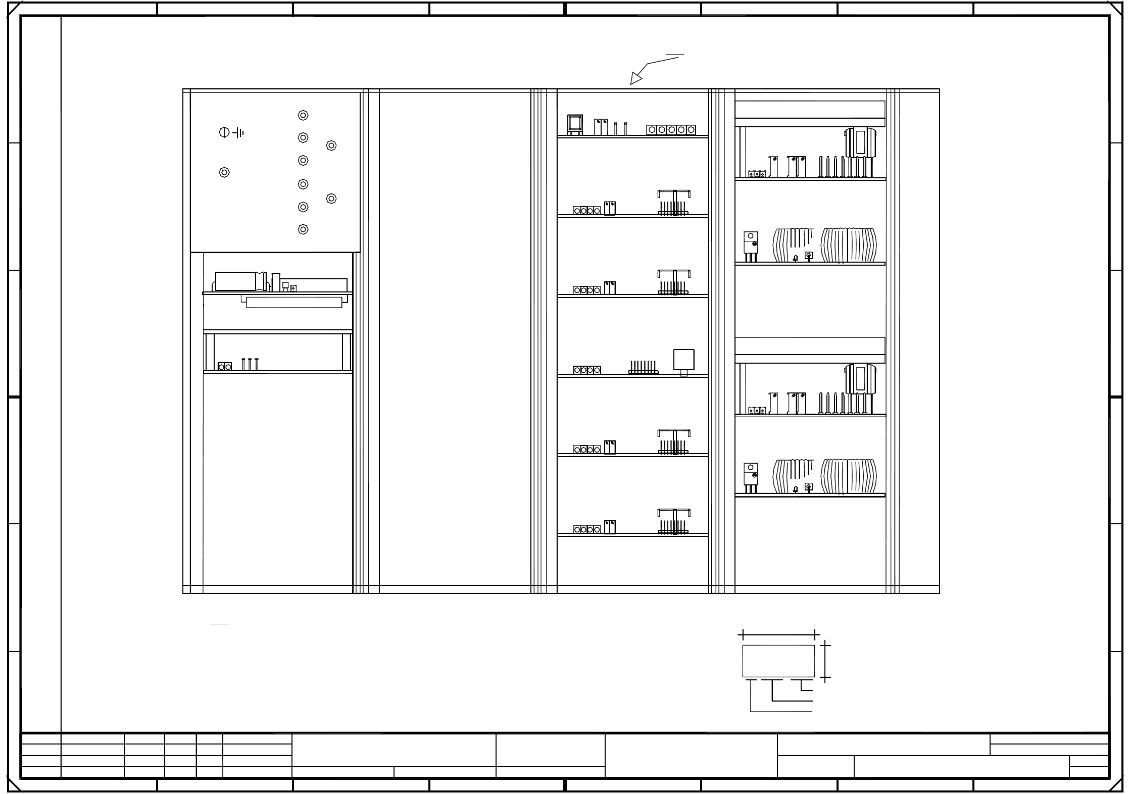
2 Circuit Diagrams 77
00345821-010101TD3 Assemblies overview (Sh. 2 of 2)
Anti-crash board
Distance sensor
-15V
GND
+15V
5
456
-15V
Offset
Servo card, star axis,
Tacho
P gain
Fault
Ready status
I r.m.s. limiting (I2xt signal)
Power supply unit
F
21
TBS120/2,5S
Ss Sensor stop signal
0V Amplifier electronic, GND
IA Motorstellgroesse (current controller output)
Is Current nom. value (speed control output)
Ta Tachometer (actual tachometer voltage)
TDS 120A 2,5Z
2
x t signal)
Note:
C
D
Reset button
Zero point, distance sensor
TDS120/1D
Fault
Ready status
Output stage, enable
Servo card, DP1-axis,
Servo card, Z-axis,
P gain
10V correspond
Scaling:
to max. motor
Y-axis, gantry II
NS Nominal speed
0V amplifier electronic, GND
3
Usoll(U) Current reg. output
Iist(W) Current actual value
Iist(U) Current actual value
10.02.99
Tuth
#
(Assembly overview)
00345821-010101TD3
10.02.99
10.02.99
PL EA1 E
}
}
Ns Nominal speed
Ii Current actual value
Analog voltage, distance sensor
AGND
and Y-axis, TBF 120/12 TS
SIPLACE 80F5-HM
Deu
Deu
Deu
01
01
01
Function status
Product status
Document status
10.02.99
Heat sink installed for Z-axis only
+15V
E
Iu Current monitor, phase U
X-axis, gantry II
E
D
C
B
A
876
B
A
2
besondere fuer den Fall der Patenterteilung oder GM-Eintragung.
X-axis, gantry I
FD Fault diagnosis
Servo card, X-axis, TBF 120/7 TS
Y-axis, gantry I
Amplification, distance sensor
F
Ni Actual speed
Tachometer
I r.m.s. limiting
Ie Nominal power input
(I
Is Current, nominal value (output, speed control)
Iv Current monitor, phase V
4321
SMD Placement System
2
87
Scaling:
of device
to max. current
Is(W) Current nom. value
Is(U) Current nom. value
Usoll(W) Current reg. output
Spare
0V Reference potential
+
Sh.
SIEMENS AG
Zustand Aenderung Datum Name Ers. d.Ers. f.Urspr.
Sheet
Bearb.
Norm
Gepr.
Datum
=
Output stage, enable
I r.m.s. limiting
Fault
(I²
Ready status
x t signal)
10V correspond
voltage
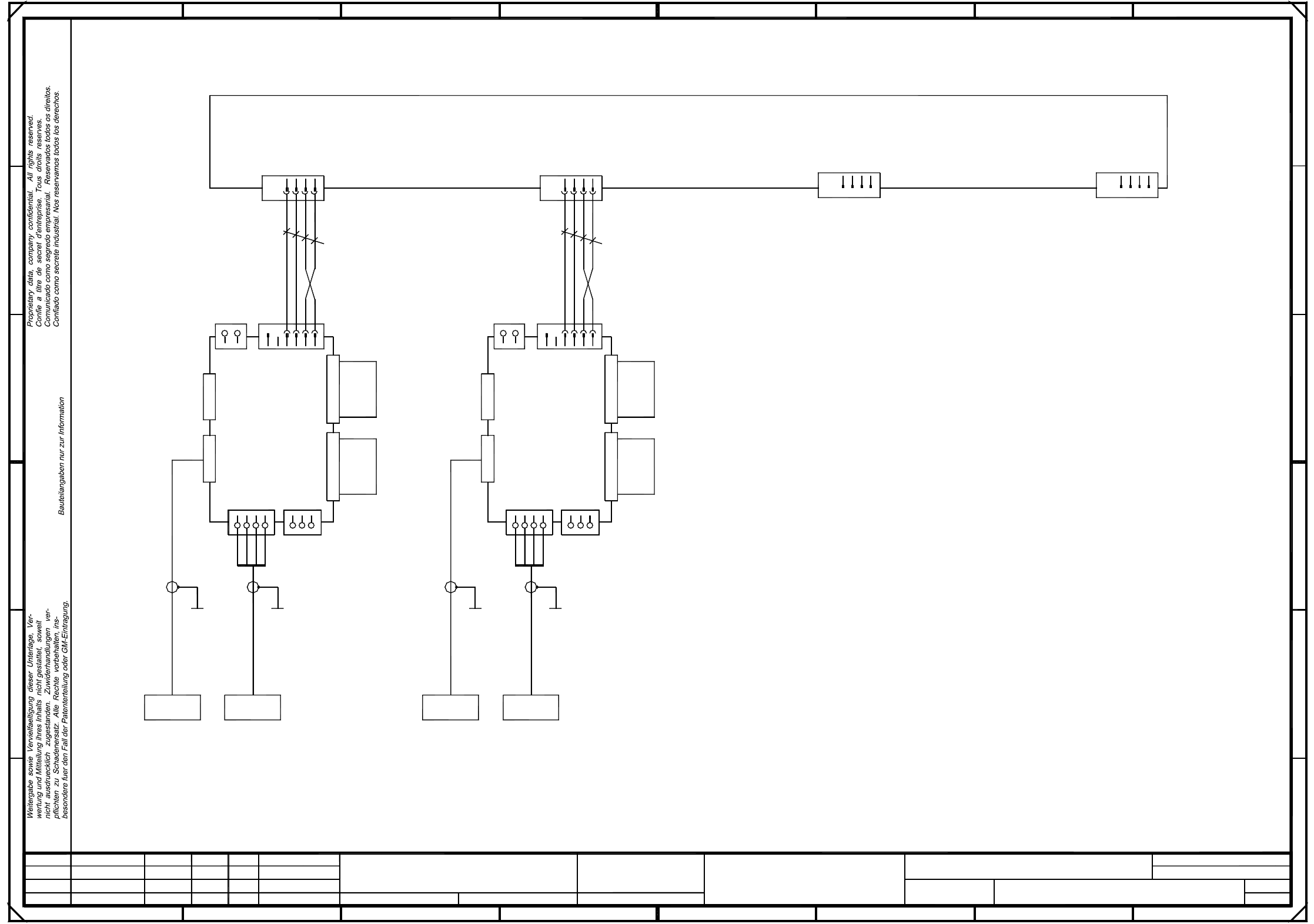
2 Circuit Diagrams 78
00345822-010101LD3 Circuit diagram, F5 HM base (Sh. 1 of 4)
=
Datum
Gepr.
Norm
Bearb.
Sheet
Urspr. Ers. f. Ers. d.NameDatumAenderungZustand
SIEMENS AG
Sh.
+
X11d
X2va
Servo
Dyn.
brake
34
X4vaX5va
00346382-xx
00346381-xx
(va)
+15V
21
-15V
Ready
Tacho
GND
Key
Axis cardTacho/RSE
Backplane
X-axis
Motor W
Power GND
Motor U
12
X7vbX7va
(vb)
1
3
412
4
X11b
X11c
X5vb
X2vbX1vb
X3vbX6vb
X11a
23
X6va X3va
X1va
3
00346384-xx
00346383-xx
Backplane
Y-axis
A14
2
+15V
-15V
1
2
SMD Placement System
1
Motor V
1
234
Axis cardTacho/RSE
123
Motor U
Power GND
Power +Ub
Power GND
Servo
A13
Power GND
Power +Ub
Motor V
Power GND
Dyn.
Tacho
Ready
+15V
34
X4vb
2
X8va
654 8
+15V
brake
12
3
4
1
4
X8vb
1
Anti-crash card A12
0,25mm²
1234 1
ye/bk
34
GND
1
ye/bk
A
Motor W
Power GND
1
Key
4
E
D
C
B
A
2
78
D
E
FF
bl
br
00337333-01
ye/gn
bk
0,25mm²
7
SIPLACE 80F5-HM
6
ye/gn
bk
32
X32a X31a
Deu
Deu
01
01
01
Function status
Product status
Document st.
10.02.99
10.02.99
10.02.99
10.02.99
Tuth
#
Circuit diagram
00345822-010101LD3
bl
br
5
X38aa X36aa
B
C
23
PL EA1 E
Deu
F5 HM servo unit, base