F5HM Circuit Diagrams.pdf - 第27页
1 Detailed Circuit Diagr ams 27 IC-V entil Pick&Place- head / valves Aend erung Zust and Datu m CAD-Datei : IC-VENTIL.DW G Urspr./Ers .f./Ers.d. Norm Name Gepr. Strom laufpla n/Circu it di agra m PL EA Mat.-Nr. : Bea…
1 Detailed Circuit Diagrams 26
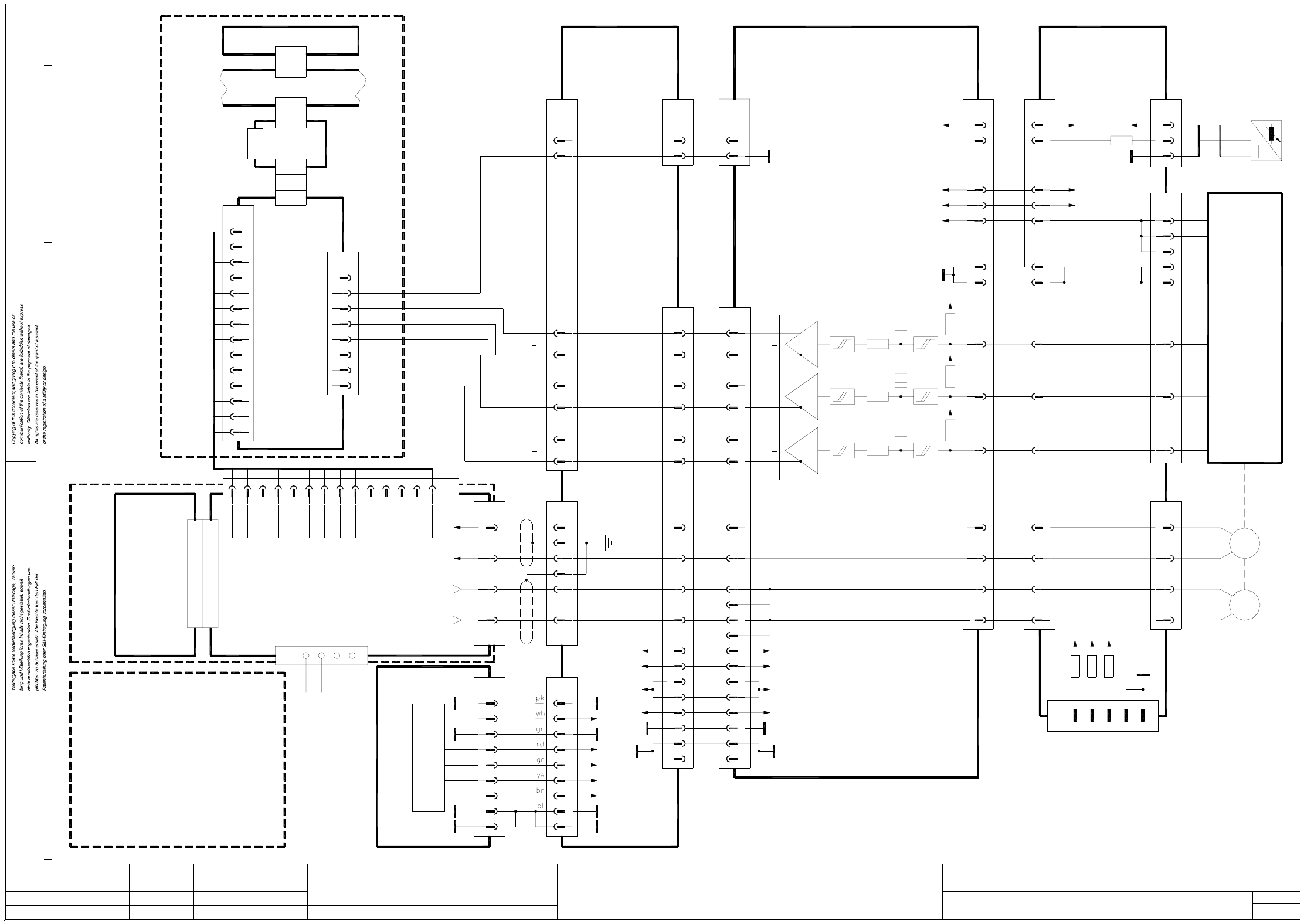
IC-Z-F5HM Pick&Place-head / Z-axis
14
2
1
3
4
5
Screen
Force
Tacho-std or f/V
Analog GND
GND Servo
V nom
Screen
Ia monitor
Sensor stop
I²t
Servo ready
Servo Enable -
Servo Enable + (+15V from Servo)
Screen
IC-Z-axis
backplane
A19 (vk)
Servo unit
00334646-xx
X1sa
X1su
X5su
X1tq
SMP bus A32 (su)
X2tq
X24
X7uc
X3tq
Axis board
A8 (tq)
Machine controller M54 A1 (sa)
IC-Z-axis
Nominal values
14
13
12
11
10
9
8
7
6
5
4
3
2
X2uc
1
11
9
8
6
5
3
2
13
X1uc
Axis tracks
IC-Z-axis
Axis rear panel A29 (uc)
00346057-xx
Control unit
00345179-xx
Cable 00345504-xx
rd
SIPLACE F5-HM
Tacho (-)2a
Tacho (+)2c
+ 15 V4a
- 15 V4c
GND Servo6a
8a
Servo ready8c
12a
Servo Enable14c
I²t16c
M-18a,c
M-20a,c
22a,c
24a,c
26a,c
28a,c
M+30a,c
M+32a,c
X1 Plug assignment/servo amplifier
10c Analog GND
Servo unit
00345821-xx
+ 15 V
12c
14a
16a
4
3
IC-Z-axis A7
X11am 1332 91
R
R
R
Ia monitor
nom
V
Force
Sensor stop
Power (0V)
Power (0V)
Power (+Vb)
Power (+Vb)
(ac)(aa)
Servo amplifier
00321796-xx
(W2-Cable)
13
8 8
Sensor stop
Reference bero
Sensor stop
Reference bero
3232
25 25
Track A
F452-W1
(Cable)
19
10
31
1616
31
19
10
+24V+24V
GNDGND
+24V+24V +24V
IC-head board
00321523-xx
br
bk
bl
6
3
9
7
2
GND
+5V
30
+5V
30
+5V
AenderungZustand Datum
CAD-Datei : IC-Z-F5HM.DWG
Urspr./Ers.f./Ers.d.NormName
Gepr.
Stromlaufplan/Circuit diagram
PL EA
Mat.-Nr. :
Beab. Hi
Datum 08.01.2001
SIEMENS
Sh.
Sh.
SMD Placement System SIPLACE F5 HM
1
1
Pick&place head / Z-axis
8
4
2
1
3
X33aa
X12aa
1
2
3
4
5
6
7
8
9
-15V
+15V
+5V
+24V
+5V
X3vk
X18
T+
T-
M+
M- wh
br
wh
br
(W1-Cable)
00321796-xx
(Cable)
00344217-xx
(Cable)
00345506-xx
X1
X1vk
00324488-xx
Power supply
Control unit
00345179-xx
+5V
-15V
+15V
+24V
+5V
4321X4vk
+30V
GND
-15V
+15V
13
X2vk
11
10
9
8
7
6
12
Incremental shaft encoder
7
X5am
1
8
1
X4am
Track B
8
10
Track N
X1am
9
16
19
22
+15V
-15V
31
33
29
18
17
3
+5V
+5V
Track N
Track N
Track A
Track A
Track B
Track B
20
18
17
14
15
28
25
13
22
Tacho +
Tacho -
z motor +
z motor -
+15V
-15V
+5V
00354430-xx
Gantry head distribution board F5 HM
(Cable)
00322257-xx
9
X2aa
11
X21aa
00336690-xx
gantry
Conversion board
25
28
13
22
7
15
11
12
8
14
17
18
21
20
X8aa
-15V
+15V
+5V
00322265-xx
(Cable)
8
9
6
5
2
3
Track B
Track B
Track A
Track A
Track N
Track N
7
1
2
2
Track A
Track B
Track N
X5am
4
3
6
5
MT
wh
bl
rd
swrt
(Cable)
F452-W2
M-
M+
T+
T-
Track A
Track B
Zero pulse
(Track N)
X11ac
3
2
17
18
29
31
33
22
19
16
9
7
8
12
11
X6ac
21
X2ac
9
-15V
+15V
+5V
T
-
+
A1
bero
Z-axis
bl
br
bk
F452-W3
(Cable)
F452-W4
(Cable)
9
6
(am)
2
3
10
11
14
13
26LS31
R4
R5
R6
R3
R2
R1
TDS 120 / A2 Z
00320854-xx
X1:33 X1:31 X1:29
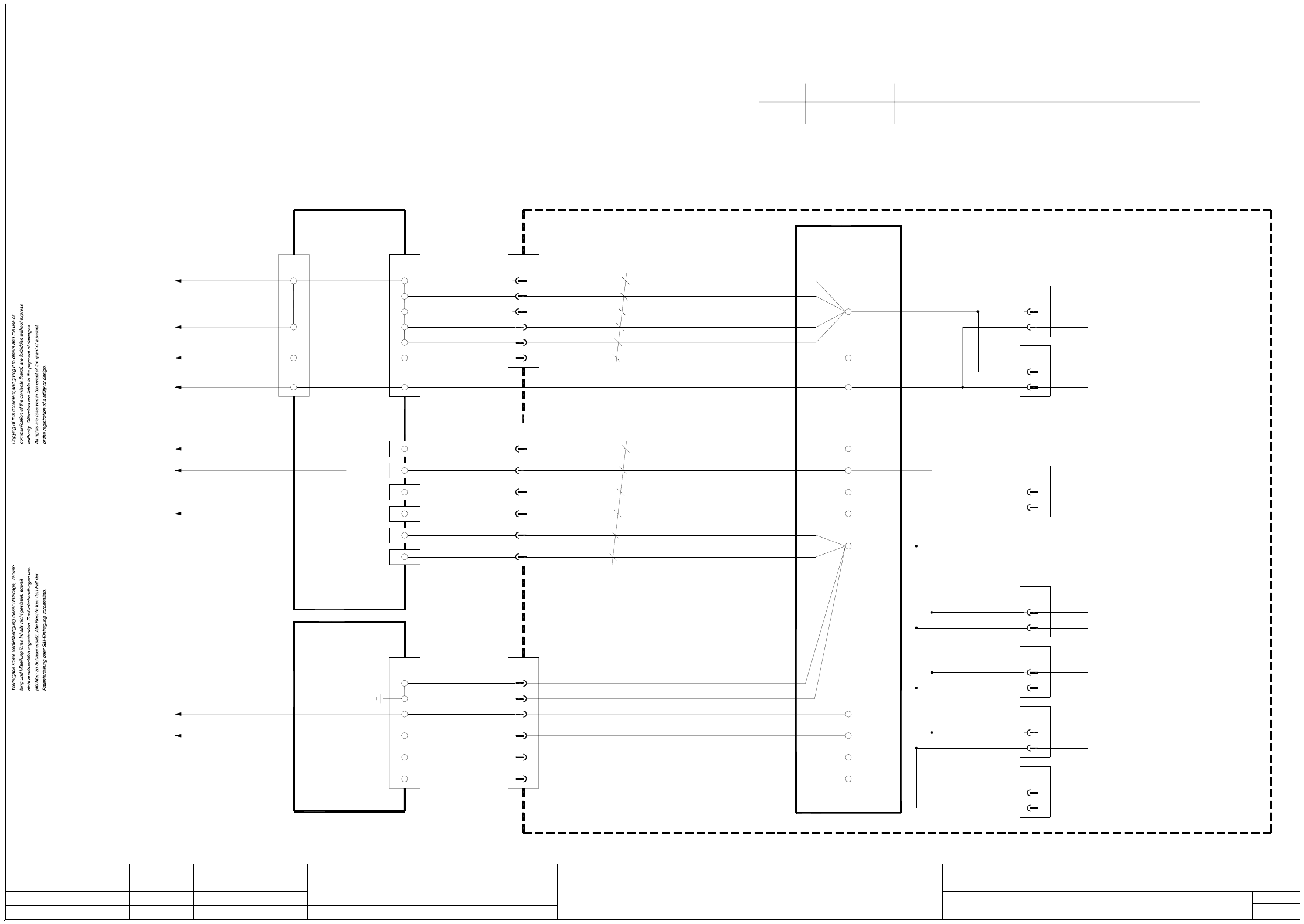
1 Detailed Circuit Diagrams 27
IC-Ventil Pick&Place-head / valves
AenderungZustand Datum
CAD-Datei : IC-VENTIL.DWG
Urspr./Ers.f./Ers.d.NormName
Gepr.
Stromlaufplan/Circuit diagram
PL EA
Mat.-Nr. :
Beab. Hi
Datum 08.01.2001
SIEMENS
Sh.
Sh.
SMD Placement System SIPLACE F5 HM
1
1
Pick&place head
valves
+
X53
-
-
X52
+
-
X54
+
Magnetic valve,
DR-axis clamping device
Magnetic valve,
forced air
Magnetic valve,
vacuum
3
X8am
1
X9am
X7am
key
key
key
6
1
3
4
1
3
5
rd
bk
rd
bk
bk
bk
(cable)
F539-W1
F540-W1
(cable)
F455-W1
(cable)
7
X1am
9
8
6
+24V
+24V
+24V
00321523 (am)
IC head board
6
8
7
X11ac
9
X24
21
23
X2
A_BLASLUFT_IC
A_VAKUUM_IC
00354430-xx (ac)
Gantry head distribution board F5 HM
00344485-xx
Processor board
+24V
6
5
3
MP6_10
MP6_10
MP6_10
X2ac
66
X2aa
(cable)
00322257-xx
14
X2aa
Gantry conversion board
00336690-xx
(ac)
00345507-xx
(cable)
14
X3uc
Axis rear panel
A29 (ue)
00346057-xx
A19
X7uc
00345179-xx
Control unit
1 Detailed Circuit Diagrams 28
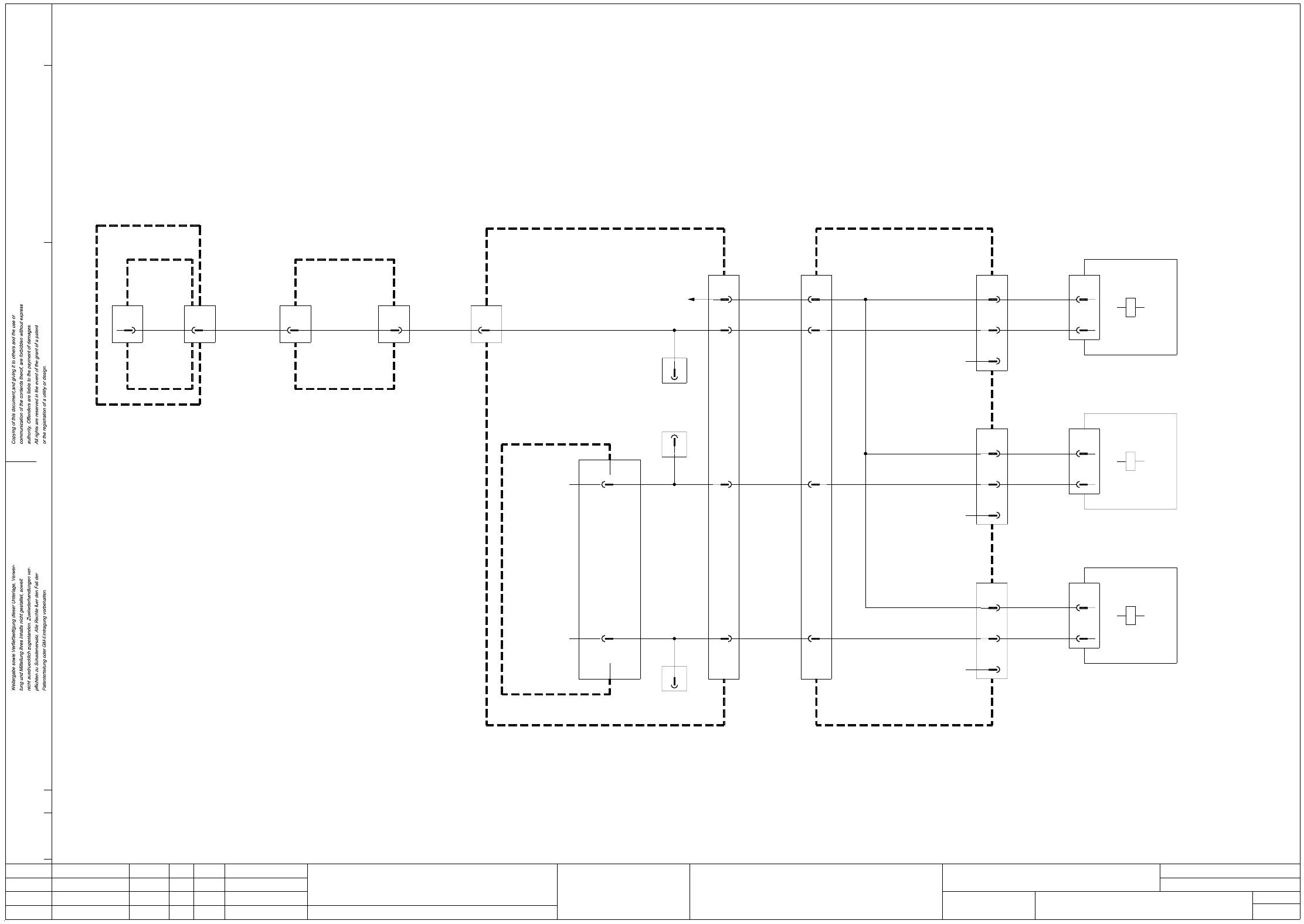
SERVF5HM1 Power supply unit for servo amplifier, anti-crash board, SIPLACE F5 HM
X4vf
brbk
wh
GND
+30V4
3
Backplane A16 Z axis,
X4vd
brbk
wh
GND
+30V4
3
Backplane A17, star axis
X4vc
pk
wh
GND
+10/70V4
3
Backplane A14, Y axis
X7vb
vi
wh
GND
+0/155V3
1,2
Backplane A13, X axis
X7va
vi
wh
GND
+0/155V3
1,2
vi
vi
2
1
X2
4
3vi
vi
5
6pk
vi
5
6
4
3
wh
wh
yebk
pk
X3
2
1
brbk
gr
15
15
13
14
14
18
19
X207
00300163-xx
(Cable)
(Cable)
00300164-xx
Star point
009
1L+/5L+
2L+
008
1L-
007
7L+
003
6L+
002
2L+/5L+
+12V
005
001
1L-
007
Potential distribution
board
00300398-xx
0VDC/+155VDC
0VDC/+155VDC
0VDC/+155VDC
0VDC/+155VDC
0VDC/+155VDC
+70VDC
GND
+30VDC switched
+30VDC unswitched
+10VDC/70VDC
+12VDC unswitched
GND 70V
GND 10V
1,5mmý
00343723-xx
1,5mmý
10mmý
AenderungZustand Datum
CAD-Datei : SERVF5HM1.DWG
Urspr./Ers.f./Ers.d.NormName
Gepr.
Stromlaufplan/Circuit diagram
PL EA
Mat.-Nr. :
Beab. Hi
Datum 08.01.2001
SIEMENS
Sh.
Sh.
SMD Placement System SIPLACE F5 HM
1
2
Power supply for servo amplifier
anti-crash board, SIPLACE F5 HM
Backplane A18 DR axis,
X4vg
brbk
wh
GND
+30V4
3
Backplane A15 DP axis,
Servo unit
righthand side
Terminal strip
X207
16
19
18
17
To power supply unit
00336812-xx
lefthand side
X211/X212
To terminal strip
00300161-xx
(Cable)
00300161-xx
00300161-xx
(Cable)
00300161-xx
00300161-xx
bk
gn
(Cable)
K0504-W1
C0511-W1
11,4
1,2
3
10
9
A4/X2:2
A4/X2:8
X207:2
A3/X2:9
A4/X2:5
A2/X2:5
Servo unit
00345821-xxF5 HM 00344266-xx
Terminal strip (lefthand side)
00337342-xx
Terminal strip (righthand side)
(Cable)
(Cable)
(Cable)
(Cable)
1
5
4
3
6
2
6
5
4
3
2
1
4blbk
3grbk
6wh
5wh
X4
wh + br
gn + ye
gr + pk
bk
006
+5V
004
+24V
+5VDC
+24VDC4
X212
10
3
3
lefthand side
Terminal strip
00344213-xx
(Cable W2)
bl + rd
To control unit
To power supply unit
(Cable)
00321113-xx
whye + whgn
00336812-xx
003
7L+
6L+
002
+30VDC unswitched
+30VDC switched
2
1rd
bl 1
2
brbk
gr
00300182-xx
(Cable)
collect&place head
collect&place head
collect&place head
pick&place head
+30V
GND
brbk
X4vk
wh 3
4
pick&place head
Backplane A19 Z axis,