F5HM Circuit Diagrams.pdf - 第54页
2 Circuit Diagr ams 54 001 17251-0 10101FD3 SIPLACE F5 HM , basic mod ule, I/O assignme nt (Sh. 2 of 2) Input Input X2sg: 9 A6/X5ki:19 X3sg: 7 X3sg:13-14 X4sg: 1-4(*) X3sg:12 X3sg: 9 X3sg:10 X3sg:11 X3sg: 8 A6/X5ki:8 A6/…
2 Circuit Diagrams 53
00117251-010101FD3 SIPLACE F5 HM, basic module, I/O assignment (Sh. 1 of 2)
X2se: 6
X2se: 5
X2se: 8
X2se: 7
Plug design.
A1/X2ka:6
A1/X2ka:7
A1/X2ka:8
A1/X2ka:M
A2/X2kc:2
A2/X2kc:1
A2/X2kc:P
X2se:11
X2se:10
X2se:12
X3se: 1-4
X3se: 6
X3se: 5
X2se:13-14
A2/X2kc:7
A2/X2kc:6
A2/X2kc:5
A2/X2kc:4
A2/X2kc:8
A2/X2kc:M
A1/X2kb:P
X3se: 8
X3se: 9
X3se:11
X3se:10
X3se:12
X4se: 1-4(*)
X3se:13-14
A2/X2kc:3X3se: 7
A1/X2ka:5X2se: 9
Input
Port E1.4
Port E1.6
Port E1.7
Port E1.5
Port E1.2
Port E1.3
Port E1.0
Port E1.1
Input
Port E2.4
Port E2.6
Port E2.5
Port E2.3
Port E2.2
Port E2.1
Port E2.0
GND
Limit switch, width adjustment, conveyor 1
Bero, stopper 1 retracted, conveyor 1
Bero, stopper 2 retracted, conveyor 2
Bero, position width adjustment, conveyor 1
Bero, lifting table bottom position, conveyor 1
Bero, lifting table top position, conveyor 1
Bero, ceramic substrate centering, conveyor 1
Contactor monitoring (software release)
+24VDC
Key-operated switch, 0 -> actuated
EMERG.-STOP button, 1 -> actuated
’Off’ button, 0 -> actuated
Control on, 1 -> K3/K4 on
Protective cover, 1 -> opened
’On’ button, 1 -> actuated
Compressed air sensor, 1 -> compressed air available
Port E2.7
GND
Control on, 1 -> K1/K2 on
A1/X2kb:1
A1/X2kb:2
A1/X2kb:3
A1/X2kb:4
A1/X2kb:6
A1/X2kb:7
A1/X2kb:8
A1/X2kb:M
A1/X2kb:5
X4se: 6
X4se: 5
X4se: 8
X4se: 7
X4se:10
X4se:12
X4se:11
X4se: 9
X4se:13-14
A2/X2kd:2
A2/X2kd:1
A2/X2kd:P
A2/X2kd:7
A2/X2kd:6
A2/X2kd:5
A2/X2kd:4
A2/X2kd:3
X5se: 6
X5se: 5
X5se: 8
X5se: 7
X5se:10
X5se:11
X5se: 9
X5se: 1-4(*)
A2/X2kd:8
A2/X2kd:M
X5se:12
X5se:13-14
Pins marked with an ’*’ are not hard-wired !
C
B
A
23
FF
E
D
67
45
1 67
B
C
D
E
8
12345
Tek
Tek
Tek
01.
01.
01.
17.07.98
17.07.98
17.07.98
17.07.1998
Tekin
00117251-010101FD3
8
A
1
2
SMD-Placement System SIPLACE 80 F5
Product status
Doc. status
Function status
I/O assignment
SIPLACE 80 F5, basic module
X5se:13-14
X5se:12
A2/X2kd:M
A2/X2kd:8
X5se: 1-4(*)
X5se: 9
X5se:11
X5se:10
X5se: 7
X5se: 8
X5se: 5
X5se: 6
A2/X2kd:3
A2/X2kd:4
A2/X2kd:5
A2/X2kd:6
A2/X2kd:7
A2/X2kd:P
A2/X2kd:1
A2/X2kd:2
X4se:13-14
X4se: 9
X4se:11
X4se:12
X4se:10
X4se: 7
X4se: 8
X4se: 5
X4se: 6
A1/X2kb:5
A1/X2kb:M
A1/X2kb:8
A1/X2kb:7
A1/X2kb:6
A1/X2kb:4
A1/X2kb:3
A1/X2kb:2
A1/X2kb:1
GND
+24VDC
GND
X2se: 9 A1/X2ka:5
X3se: 7 A2/X2kc:3
X3se:13-14
X4se: 1-4(*)
X3se:12
X3se:10
X3se:11
X3se: 9
X3se: 8
A1/X2kb:P
A2/X2kc:M
A2/X2kc:8
A2/X2kc:4
A2/X2kc:5
A2/X2kc:6
A2/X2kc:7
X2se:13-14
X3se: 5
X3se: 6
X3se: 1-4
X2se:12
X2se:10
X2se:11
A2/X2kc:P
A2/X2kc:1
A2/X2kc:2
A1/X2ka:M
A1/X2ka:8
A1/X2ka:7
A1/X2ka:6
X2se: 7
X2se: 8
X2se: 5
X2se: 6
X2se: 1-4
A1/X2ka:4
A1/X2ka:3
A1/X2ka:2
A1/X2ka:1
A1/X2ka:P
+24VDC
=
Datum
Gepr.
Norm
Bearb.
Blatt
Urspr. Ers. f. Ers. d.NameDatumAenderungZustand
SIEMENS AG
Bl.
+
PL EA1 E2
GND
MC1 (M44)
Icos MC1
+24VDC
GND
+24VDC
X5sf:13-14
X5sf:12
A4/X5kg:M
A4/X6kg:8
GND
X5sf: 1-4(*)
X5sf: 9
X5sf:11
X5sf:10
X5sf: 7
X5sf: 8
X5sf: 5
X5sf: 6
A4/X4kg:15
A4/X6kg:7
A4/X6kg:6
A4/X6kg:5
A4/X4kg:14
A4/X5kg:P
A4/X3kg:18
A4/X3kg:19
X4sf:13-14
X4sf: 9
X4sf:11
X4sf:12
X4sf:10
X4sf: 7
X4sf: 8
X4sf: 5
X4sf: 6
A3/X2kf:5
A3/X2kf:M
A3/X2kf:8
A3/X2kf:7
A3/X2kf:6
A3/X2kf:4
A3/X2kf:3
A3/X2kf:2
A3/X2kf:1
+24VDC
GND
X2sf: 9
A4/X4kg:19X3sf: 7
X3sf:13-14
X4sf: 1-4(*)
X3sf:12
X3sf:10
X3sf:11
X3sf: 9
X3sf: 8
A4/X5kg:M
A4/X5kg:8
A3/X2kf:P
A4/X5kg:7
A4/X5kg:6
A4/X5kg:5
A4/X4kg:18
X2sf:13-14
X3sf: 1-4
X3sf: 5
X3sf: 6
X2sf:12
X2sf:10
X2sf:11
A4/X5kg:G
A4/X3kg:14
A4/X3kg:15
+24VDC
GND
GND
X2sf: 1-4
X2sf: 7
X2sf: 8
X2sf: 5
X2sf: 6
Address
Port A3.2
Port A3.3
Port A3.1
Port A3.0
Port A3.7
Port A3.6
Port A3.5
Port A4.1
Port A4.0
Output
Port A4.7
Port A4.6
Port A4.5
Port A4.4
Port A4.3
Port A4.2
Output
Port A3.4
Signal designation
+30VDC switched
Motor, spare, on slow
Motor, spare, on fast
Conversion
board,
X2sf: 6
X2sf: 5
X2sf: 8
X2sf: 7
X2sf: 1-4
Plug design. I/O terminal
GND
+30VDC switched
GND
+24VDC
Motor, width adjustment wider, conveyor 1
Motor, width adjustment fast, conveyor 1
Component counter
A4/X3kg:15
A4/X3kg:14
A4/X5kg:G
X2sf:11
X2sf:10
X2sf:12
X3sf: 6
X3sf: 5
X3sf: 1-4
X2sf:13-14
A4/X4kg:18
A4/X5kg:5
A4/X5kg:6
A4/X5kg:7
A3/X2kf:P
A4/X5kg:8
A4/X5kg:M
X3sf: 8
X3sf: 9
X3sf:11
X3sf:10
X3sf:12
X4sf: 1-4(*)
X3sf:13-14
X3sf: 7 A4/X4kg:19
X2sf: 9
PCB handling
Motor, center conveyor on slow, conveyor 1
Motor, center conveyor on fast, conveyor 1
Motor, PCB input conveyor on fast, conveyor 1
Motor, output conveyor on fast, conveyor 1
Motor, output conveyor on slow 2, conveyor 1
Motor, output conveyor on slow 1, conveyor 1
’Received’ to previous station from conveyor 1
’Permission’ to previous station from conveyor 1
Motor, width adjustment narrower, conveyor 1
’Transferred’ to following station from conveyor 1
’Request’ to following station from conveyor 1
Input
Port E3.4
Port E3.6
Port E3.7
Port E3.5
Port E3.3
Port E3.2
Port E3.1
Port E3.0
Input
Port E4.4
Port E4.6
Port E4.5
Port E4.3
Port E4.2
Port E4.1
Port E4.0
Port E4.7
Distance sensor
Crash, portal 1
GND
Bero, nozzle changer SP, portal 2 opened
Bero, nozzle changer SP, portal 1 opened
Bero, nozzle changer SP, portal 1 closed
Bero, nozzle changer SP, portal 2 closed
+24VDC
A3/X2kf:1
A3/X2kf:2
A3/X2kf:3
A3/X2kf:4
A3/X2kf:6
A3/X2kf:7
A3/X2kf:8
A3/X2kf:M
A3/X2kf:5
X4sf: 6
X4sf: 5
X4sf: 8
X4sf: 7
X4sf:10
X4sf:12
X4sf:11
X4sf: 9
X4sf:13-14
A4/X3kg:19
A4/X3kg:18
A4/X5kg:P
A4/X4kg:14
A4/X6kg:5
A4/X6kg:6
A4/X6kg:7
A4/X4kg:15
X5sf: 6
X5sf: 5
X5sf: 8
X5sf: 7
X5sf:10
X5sf:11
X5sf: 9
X5sf: 1-4(*)
GND
A4/X6kg:8
A4/X5kg:M
X5sf:12
X5sf:13-14
Pins marked with an ’*’ are not hard-wired !
Ultrasonic sensor, input conveyor, conveyor 2
Ultrasonic sensor, input conveyor, conveyor 1
Ultrasonic sensor, output conveyor, transport 1
Ultrasonic sensor, output conveyor, transport 2
’Request’ to conveyor 1 from previous station
’Transferred’ to conveyor 1 from previous station
’Permission’ to conveyor 1 from following station
’Received’ to conveyor 1 from following station
Ultrasonic sensor, center conveyor, conveyor 2
Ultrasonic sensor, center conveyor, conveyor 1
Address
Port A1.2
Port A1.3
Port A1.0
Port A1.1
Signal designation
+24VDC
Retract lifting table, PCB release, conveyor 1
Extend lifting table, PCB clamping, conveyor 1
Valve, nozzle changer 2 opened
Valve, nozzle changer 1 opened
Port A1.7
Port A1.5
Port A1.6
Port A2.1
Port A2.0
Output
Port A2.7
Port A2.6
Port A2.5
Port A2.4
Port A2.3
Port A2.2
GND
+24VDC
Valve, ceramic substrate centering, conveyor 1
Valve, extend stopper 2, conveyor 2
Lamp, main fault indicator ready (green)
Valve, extend stopper 1, conveyor 1
Icos MC1
MC1 (M44)
GND
+24VDC
Software release, control on
Lamp, main fault indicator lefthand side (white)
Command ’read PCB barcode’ 2 (contactor relay)
Command ’read PCB barcode’ 1 (contactor relay)
Lamp, main fault indicator righthand side (white)
Output
Compressed air on/off Port A1.4
I/O terminal
A1/X2ka:P
A1/X2ka:1
A1/X2ka:2
A1/X2ka:3
A1/X2ka:4
X2se: 1-4
2 Circuit Diagrams 54
00117251-010101FD3 SIPLACE F5 HM, basic module, I/O assignment (Sh. 2 of 2)
Input Input
X2sg: 9
A6/X5ki:19X3sg: 7
X3sg:13-14
X4sg: 1-4(*)
X3sg:12
X3sg: 9
X3sg:10
X3sg:11
X3sg: 8
A6/X5ki:8
A6/X5ki:M
A6/X5ki:18
A6/X5ki:5
A6/X5ki:6
A6/X5ki:7
X2sg:13-14
X3sg: 5
X3sg: 6
X3sg: 1-4
X2sg:12
X2sg:11
X2sg:10
A6/X5ki:15
A6/X5ki:14
A6/X5ki:G
PCB handling
Plug desig.
X2sg: 7
X2sg: 8
X2sg: 5
X2sg: 6
X2sg: 1-4
Conversion
board,
I/O terminal
Motor, output conveyor on slow 1, conveyor 2
Output
Valve, ceramic substrate centering, conveyor 2
Motor, width adjustment narrower, conveyor 2
’Permission’ to previous station from conveyor 2
’Transferred’ to following station from conveyor 2
’Request’ to following station from conveyor 2
Motor, width adjustment wider, conveyor 2
Motor, width adjustment fast, coveyor 2
+24VDC
GND
+30VDC switched
’Received’ to previous station from conveyor 2
Motor, output conveyor on fast, conveyor 2
Motor, output conveyor on slow 2, conveyor 2
Motor, input conveyor on fast, conveyor 2
GND
Output
Extend lifting table, PCB clamping, conveyor 2
Retract lifting table, PCB release, conveyor 2
Motor, center conveyor on slow, conveyor 2
Motor, center conveyor on fast, conveyor 2
Signal designation
+24VDC
Address
Port E6.7
Port E6.1
Port E6.3
Port E6.2
Port E6.6
Port E6.5
Port E6.4
Port E6.0
Port E5.1
Port E5.0
Port E5.2
Port E5.3
Port E5.5
Port E5.7
Port E5.6
Port E5.4
Port A5.4
Port A6.2
Port A6.4
Port A6.3
Port A6.6
Port A6.5
Port A6.7
Port A5.6
Port A5.5
Port A5.7
Port A6.1
Port A6.0
Port A5.1
Port A5.0
Port A5.3
Port A5.2
=
Datum
Gepr.
Norm
Bearb.
Blatt
Urspr. Ers. f. Ers. d.NameDatumAenderungZustand
SIEMENS AG
Bl.
+
PL EA1 E2
C
B
A
23
FF
E
D
67
45
1 67
B
C
D
E
8
12345
Tek
Tek
Tek
01.
01.
01.
17.07.98
17.07.98
17.07.98
17.07.1998
Tekin
00117251-010101FD3
8
A
2
2
SMD-Placement System SIPLACE 80 F5
Product status
Doc. status
Function status
I/O assignment
SIPLACE 80 F5, basic module
Pins marked with an ’*’ are not hard-wired !
X5sg:13-14
X5sg:12
A6/X5ki:M
A6/X6ki:8
X5sg: 1-4(*)
X5sg: 9
X5sg:11
X5sg:10
X5sg: 7
X5sg: 8
X5sg: 5
X5sg: 6
A6/X5ki:15
A6/X6ki:7
A6/X6ki:6
A6/X6ki:5
A6/X5ki:14
A6/X5ki:P
A6/X5ki:18
A6/X5ki:19
X4sg:13-14
X4sg: 9
X4sg:11
X4sg:12
X4sg:10
X4sg: 7
X4sg: 8
X4sg: 5
X4sg: 6
PCB handling
Conversion
board
GND
’Transferred’ to conveyor 2 from previous station
’Permission’ to conveyor 2 from following station
’Request’ to conveyor 2 from previous station
’Received’ to conveyor 2 from following station
+24VDC
Bero, ceramic substrate centering, conveyor 2
Bero, lifting table top position, conveyor 2
Bero, lifting table bottom position, conveyor 2
Limit switch, width adjustment, conveyor 2
Bero, position width adjustment, conveyor 2
GND
2 Circuit Diagrams 55
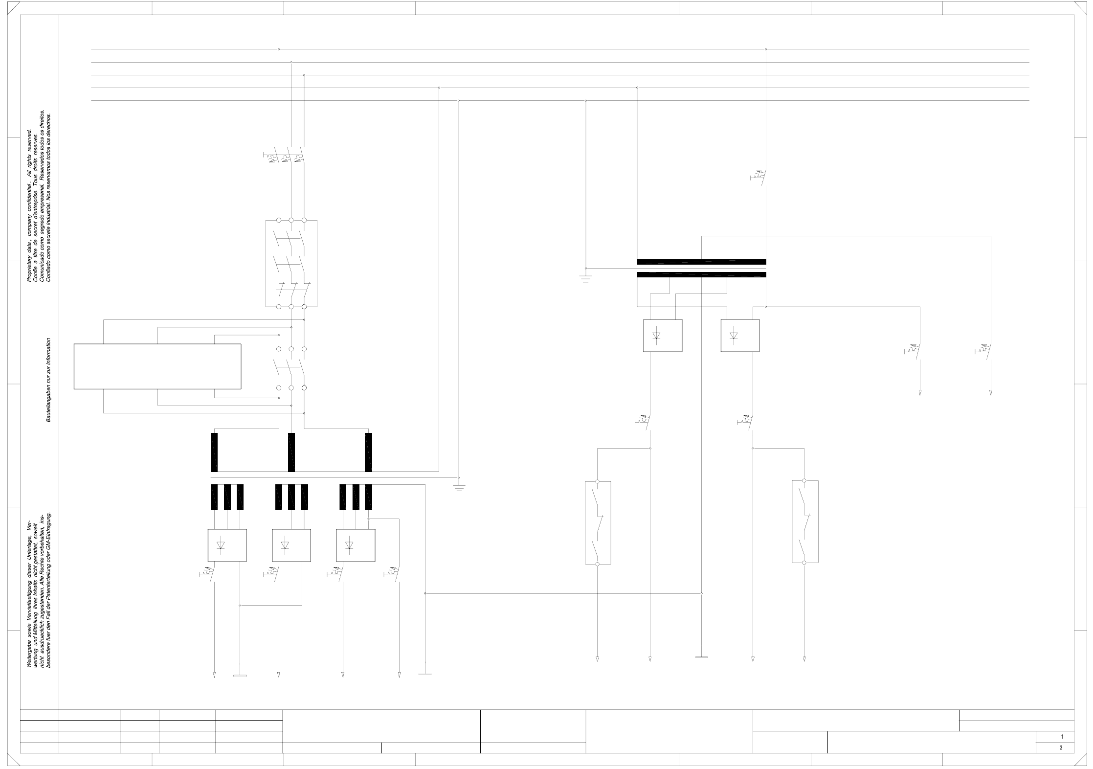
00336812-020101FD3 Circuit diagram overview, safety concept, power unit (Sh. 1 of 3)
SMD-Placement System Siplace S23
Product status
Doc. status
Function status
Safety concept (power unit)
L1
1L+
1L-
3L+2L+
4L+
V2
F7
T2
7L+
K1
L1
L2
L3
PE
N
5L+
K2
C
B
A
V4
13
K2
PE
L3
N
L2
2L-
V3
F6
V1
F9F8
F2
A1
T1
V5
14
23
FF
E
D
67
Switched
(Lifting table)
(dp1/Z axes)
(Star, slow)
(X,Y slow)
To
150VAC
safety circuit
24VAC
24VAC
(Tape cutter)
(Star/lifting table)
(X,Y axes)
45
1 67
B
C
D
E
8
12345
Leh
Leh
Leh
02
01
01
03.09.98
23.01.98
23.01.98
03.09.98
Werner
#
Circuit diagram overview
00336812-020101FD3
8
A
Switched
control unit
=
Datum
Gepr.
Norm
Bearb.
Blatt
Urspr. Ers. f. Ers. d.NameDatumAenderungZustand
SIEMENS AG
Bl.
+
PL EA1 E
To
Inrush
current limiter
(ext. WPC)
K4
F4 F5
6L+
2L-
F10 F11
F3
23
24