Nordson_EFD_RV_Series_Operating_Manual.pdf - 第115页
RV Series Automated Dispensing Systems 115 www.nordsonefd.com info@nordsonefd.com +1-401-431-7000 Sales and service of Nordson EFD dispensing systems are available worldwide. AppendixA, Command Function Refer ence (cont…
RV Series Automated Dispensing Systems
114 www.nordsonefd.com info@nordsonefd.com +1-401-431-7000 Sales and service of Nordson EFD dispensing systems are available worldwide.
AppendixA, Command Function Reference
(continued)
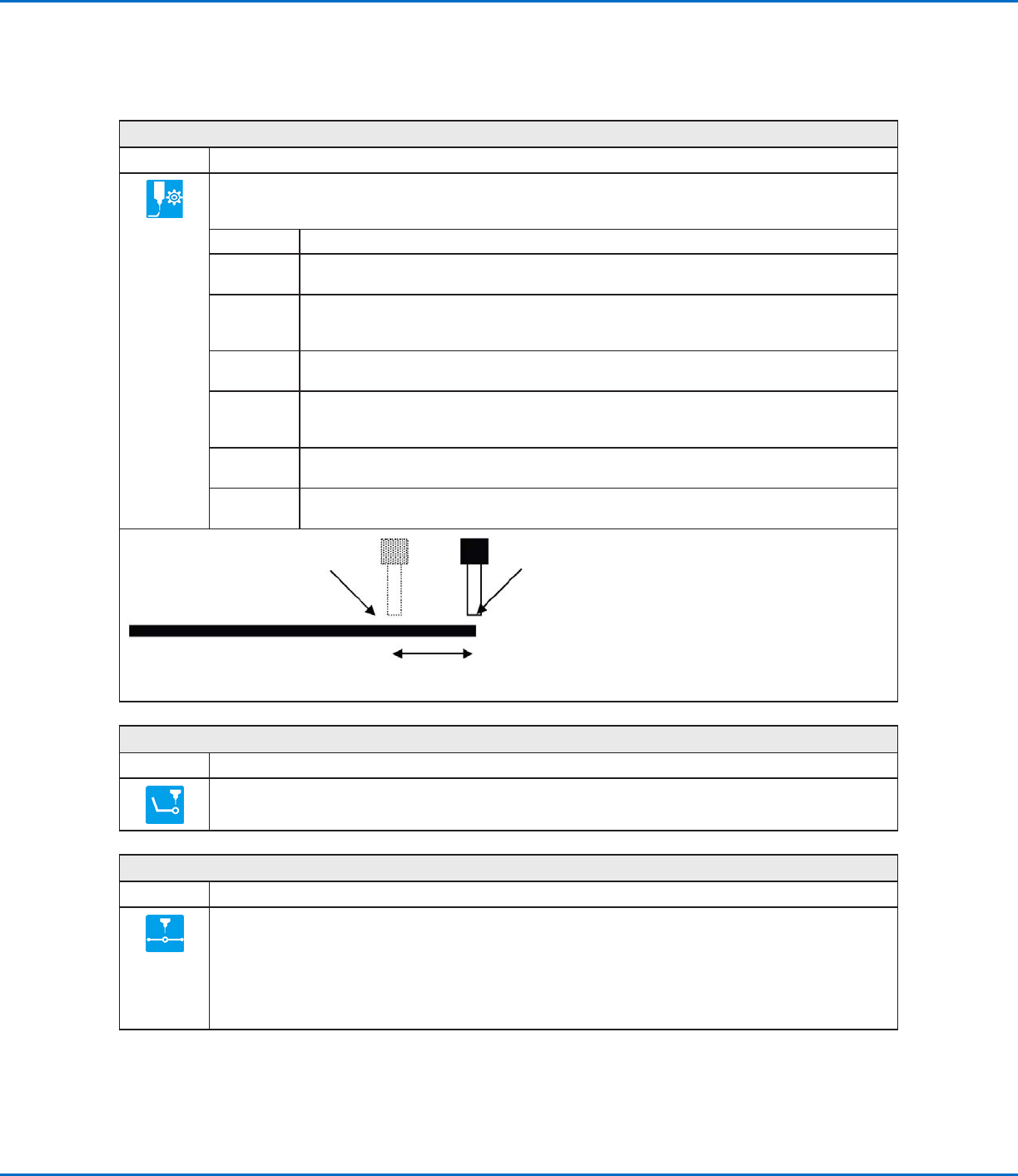
Line Dispense Setup
Click Function
Sets how the system dispenses a line of fluid. When dispensing high-viscosity fluids, there is often a delay
between when the dispenser opens and when fluid begins to flow. Use the Line Dispense Setup parameters to
compensate for this delay.
Parameter Description
Pre-move
Delay
The time the dispenser stays open at the start of a line before moving. This delay time prevents
the tip from moving along the line until fluid is flowing.
Settling
Distance
The distance the robot moves from the beginning of a Line Start before the dispenser turns on.
This distance allows the robot sufficient time to build speed and is used primarily to eliminate the
deposit of too much fluid at the beginning of a line.
Dwell Time Delay time that occurs at the end of a line after the dispenser closes to allow the pressure to
equalize before the tip moves to the next point.
Node Time Delay time that occurs only for a Line Passing command. The dispensing tip passes through
the Line Passing point and waits at the Line Passing point, with the dispenser activated, for the
specified time period.
Shutoff
Distance
The distance before the end of a line when the dispenser closes to prevent excess fluid from
being deposited at the end of the line, as shown in the illustration below.
Shutoff
Delay
The time the dispenser stays open after it stops at the end of a line.
Shutoff Distance
Tip continues moving to the end of the lineDispenser turns off here
Illustration of the Shutoff Distance parameter
Line End
Click Function
Registers the current XYZR location as a Line End point.
NOTE: The correct sequence of commands for a line is as follows: (1) Line Start, (2) Line Passing, (3) Line End.
Line Passing
Click Function
Registers the current XYZR location as a Line Passing point. This is a location on a line where the dispensing tip
changes direction, such as at the corner of a rectangle.
NOTES:
• The correct sequence of commands for a line is as follows: (1) Line Start, (2) Line Passing, (3) Line End.
• Also use a Line Passing point before and after an Arc Point command.
RV Series Automated Dispensing Systems
115www.nordsonefd.com info@nordsonefd.com +1-401-431-7000 Sales and service of Nordson EFD dispensing systems are available worldwide.
AppendixA, Command Function Reference
(continued)
Line Speed
Click Function
Sets the speed (inmm/s) at which the dispensing tip travels at the location in the program where this command
is inserted, thus overriding the default system line speed setting.
Line Start
Click Function
Registers the current XYZR location as a Line Start point for line dispensing.
NOTE: The correct sequence of commands for a line is as follows: (1) Line Start, (2) Line Passing, (3) Line End.
Loop Address
Click Function
Double-click
address and
select from
drop-down
menu
Loops the program back to a specific Address (A) or Label for the number of times set for Count.
Parameter Description
Address The Address (A) or Label number the program jumps to. The jump-to Address (A) or Label must
occur before the current address.
Count The number of times to execute the loop.
Mark Adjust
Click Function
Double-click
address and
select from
drop-down
menu
When used in tandem with the Find Mark command, causes the system to search for the mark specified in the
No. (number) field of the Find Mark command. When the system finds the mark, it checks the XY position of the
workpiece and adjusts the dispensing path accordingly.
Mark Follow
Click Function
Double-click
address and
select from drop-
down menu
When used in tandem with a Find Mark command, causes the system to dispense along a slightly curved
line. For more deeply curved lines, the Mark Follow Offset command is also needed. Refer to “How to Use
Mark Follow to Dispense Along a Curved Line” on page78 for an example of how to use this command in
a program.
Setting Description
1 Turns Mark Follow ON.
0 Turns Mark Follow OFF.
RV Series Automated Dispensing Systems
116 www.nordsonefd.com info@nordsonefd.com +1-401-431-7000 Sales and service of Nordson EFD dispensing systems are available worldwide.
Mark Follow Offset
Click Function
Double-click
address and
select from drop-
down menu
Used in tandem with a Mark Follow command to allow the system to dispense along a deeply curved line;
the offset parameters define how much offset to apply to a series of Line Passing commands. Refer to
“How to Use Mark Follow to Dispense Along a Curved Line” on page78 for an example of how to use this
command in a program.
Setting Description
X Distance (in mm) of the offset in the X direction
Y Distance (in mm) of the offset in the Y direction
Multi Needle
Click Function
Double-click
address and
select from
drop-down
menu
In multiple dispenser installations, specifies the dispenser (called Needle Number) to execute the commands that
follow this command. Currently up to four dispensers can be installed, so the Needle Number parameter can be
1–4.
NOTE: For this function to operate correctly, the additional dispensers must be installed and set up. Refer to
“AppendixE, Multi-Needle Setup and Use” on page137.
Needle XY Adjust
Click Function
Double-click
address and
select from drop-
down menu
Causes the system to perform a Needle XY Adjust (check the camera-to-tip offset) and, based on the result,
to take action as specified by the parameter settings.
NOTE: To perform the Needle XY adjust, the robot moves the dispensing tip to the Set Needle position and
dispenses a dot of fluid, then moves the camera over the fluid dot and compares the alignment of the dot
with the corresponding mark image saved in the Mark Library. The Set Needle position and mark image
were established during the Robot Initial Setup process.
Parameter Description
X range Sets the maximum offset allowed for the X axis.
Y range Set the maximum offset allowed for the Y axis.
0.Ask,
1.Continue
0. Ask The system asks if you want to update the camera-to-tip offset.
1.Continue The system automatically accepts the camera-to-tip offset (unless out of
range) and then continues to the next command.
AppendixA, Command Function Reference
(continued)