Nordson_EFD_RV_Series_Operating_Manual.pdf - 第23页
RV Series Automated Dispensing Systems 23 www.nordsonefd.com info@nordsonefd.com +1-401-431-7000 Sales and service of Nordson EFD dispensing systems are available worldwide. About Of fsets Offset is the distance between …
RV Series Automated Dispensing Systems
22 www.nordsonefd.com info@nordsonefd.com +1-401-431-7000 Sales and service of Nordson EFD dispensing systems are available worldwide.
Concepts
Before creating any programs, make sure you understand the concepts explained in this section.
About Programs and Commands
A program is a set of commands stored as a file. Each command is stored in the file as a numbered address.
Commands can be subdivided into the following command types:
• A setup command sets a program-level parameter, such as an XYZR coordinate or the Z clearance height.
• A dispense command is tied to an XYZR coordinate and automatically sends a signal to the dispensing system
to execute the dispense command.
When the robot executes a program, it steps through each address in sequence and executes the command
contained in that address. If an address contains a setup command, the system registers that command. If an
address contains a dispense command, the robot moves the X, Y, Z, and R axes to the location specified for that
command and then performs the dispense command.
Dispense commands are the building blocks of patterns. To program a dispense command, the dispensing tip is
jogged to the desired XYZR location and then a dispense command is registered for that location. This action is
repeated until the desired dispensing pattern is complete. Several examples are provided below.
Setup commands dictate how dispense commands will be executed. Nordson EFD recommends inserting setup
commands at the beginning of a program. The following setup commands are the most commonly used: Backtrack
Setup, Dispense Dot Setup, Dispense End Setup, Line Dispense Setup, Line Speed, and Z Clearance Setup.
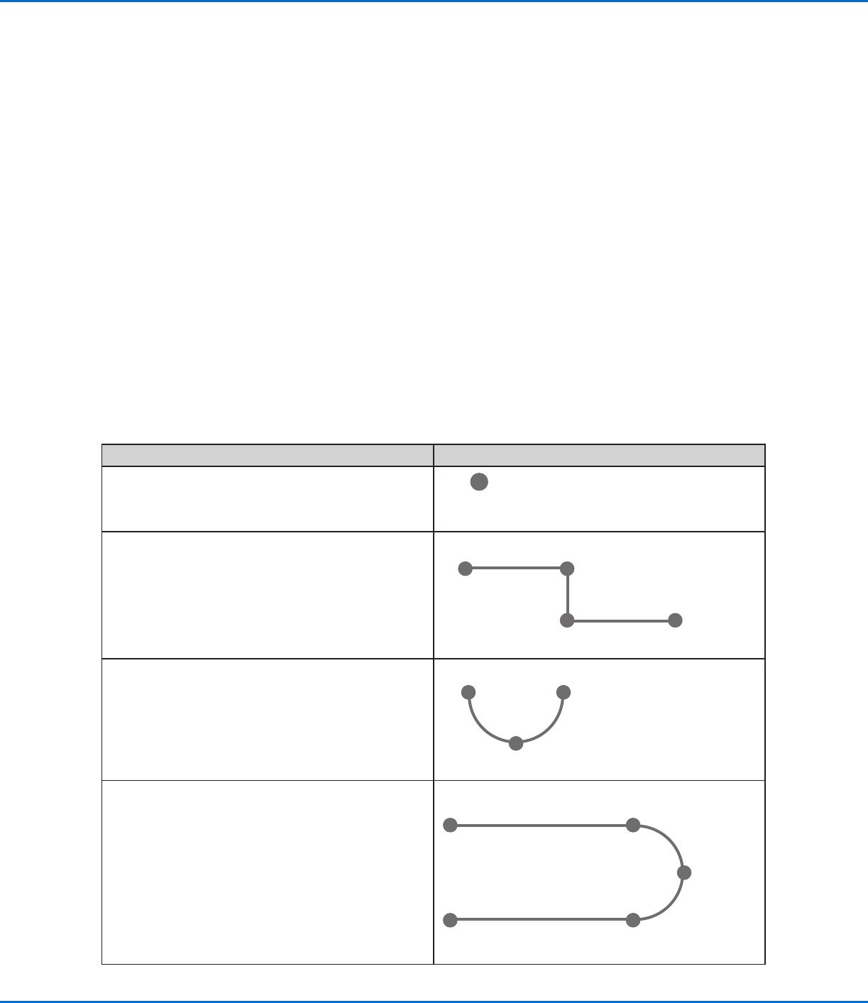
Dispense Command Examples
Commands Resulting Pattern (Overhead View)
To program the robot to dispense a dot of fluid, an
XYZR location is registered as a DISPENSE DOT
command.
DISPENSE DOT
To program the robot to dispense a bead of fluid along
a linear path, the XYZR location of the start of the line
is registered as a LINE START command. The locations
where the tip changes direction are registered as LINE
PASSING commands. The location where the bead of
fluid ends is registered as a LINE END command.
Line Start
Line EndLine Passing
Line Passing
To dispense a bead of fluid in an arc, the XYZR location
of the start of the bead is registered as a LINE START
command. The high point of the arc is registered as an
ARC POINT command. The end of the arc is registered
as a LINE END command.
Arc Point
Line Start Line End
Lines and arcs can also be combined to dispense a
bead of fluid along a complex path.
Line Start
Line End
Arc Point
Line Passing
Line Passing
RV Series Automated Dispensing Systems
23www.nordsonefd.com info@nordsonefd.com +1-401-431-7000 Sales and service of Nordson EFD dispensing systems are available worldwide.
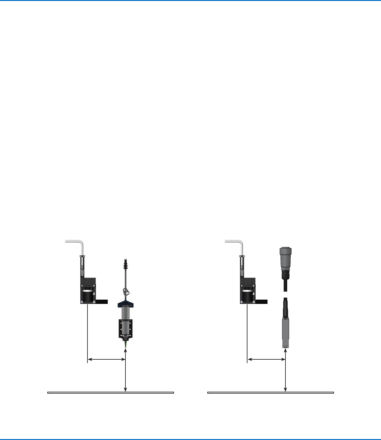
About Offsets
Offset is the distance between two components. The system must be “taught” the following offsets before any
programs are created:
• Camera-to-tip offset: the distance between the center of the camera view and the center of the dispensing tip
(this is an XY offset).
• Tip-to-workpiece offset: (1) the distance between the bottom of the tip and the workpiece for contact
applications or (2) the distance between the bottom of the nozzle and the workpiece for non-contact
applications (this is the Zclearance).
These offsets must be properly calibrated to make sure the dispensing tip follows the same path as the camera and
to compensate for slight variations in height that occur when a dispensing tip or nozzle is changed.
Offsets are taught to the robot during the setup and calibration process, which is guided by the Robot Initial Setup
wizard. This process must be performed for initial startup and also after any change to the system. Examples of
system changes include the following:
• Any time a component installed on the Zaxis (such as the syringe barrel or camera) is moved.
• Any time a dispensing tip or nozzle is changed.
About Programs and Commands (continued)
Best Practices for Programming
• Insert dispense setup commands at the beginning of the program.
• Insert mark commands before any dispense commands.
• Insert dispense commands after inserting setup and mark commands.
• Insert the End Program command at the end of all programs.
Illustration of camera-to-tip offset (also referred to as XY offset) and tip-to-workpiece offset (also referred to as tip height or
Zclearance)
Camera-to-tip
XY offset
Tip-to-workpiece
offset
(Z clearance)
Camera-to-tip
XY offset
Tip (nozzle)-to-
workpiece offset
(Z clearance)
RV Series Automated Dispensing Systems
24 www.nordsonefd.com info@nordsonefd.com +1-401-431-7000 Sales and service of Nordson EFD dispensing systems are available worldwide.
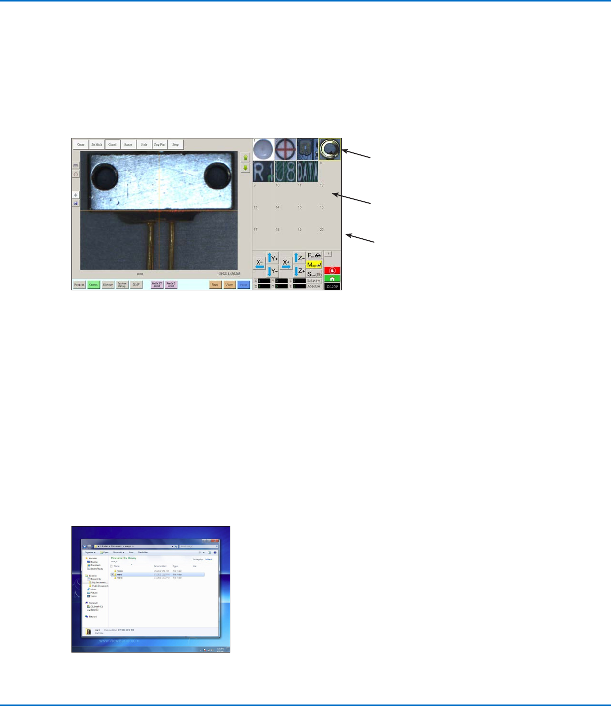
About Marks
To recognize that a workpiece is present or to determine its orientation on the fixture plate, the system uses marks
and fiducial marks. Marks are reference images (pictures of a small area on a workpiece) taken by the camera and
stored in a location called the Mark Library. The Mark Library appears in the Secondary View screen when the
Camera tab is selected. The stored images are shown in sockets in the Mark Library. Picture sockets are blank if
they do not contain a stored image.
A mark is a single image that the system uses to find a specific location on a workpiece. Fiducial marks are two
mark images that are used conjointly to (1) identify whether a workpiece is present in the proper XY location and (2)
to understand its angle of rotation, and then to make automatic adjustments to the program accordingly.
Picture socket with
a stored mark image
Blank picture
socket (no stored
image)
Location of mark image files on the DispenseMotion controller
Best Practices For Selecting a Mark Image
• The selection should be on the actual workpiece (not on the fixture plate) because it is the workpiece position that
the system adjusts to.
• The selection should be unique. There should be only one selection of its kind within the camera view. For
example, don’t choose one of many small circles that are within the camera view.
• Sharp features are best. For example, the intersection of two lines in the capital letter T would be better for a mark
image than the center of a circle, which possesses no finite lines.
• An actual dispensing position, such as the corner of a silk-screened solder pad, is more effective than the broken
corner edge of a pallet of circuit boards because of the differences in their manufacturing precision.
• The further away fiducial marks are from each other, the more precise the system will be in locating them on a
workpiece.
Mark Image Files
You can store 240 mark images in the sockets available in the Mark Library. The Mark Library appears in the
Secondary View screen (refer to “Secondary View Screen” on page30 for more information). These marks are
stored as files on the DispenseMotion controller under D:\ever_sr\mark.
Camera screen shown in the Primary View screen and the Mark Library shown in the Secondary View screen
Mark Library