Nordson_EFD_RV_Series_Operating_Manual.pdf - 第95页
RV Series Automated Dispensing Systems 95 www.nordsonefd.com info@nordsonefd.com +1-401-431-7000 Sales and service of Nordson EFD dispensing systems are available worldwide. Maximum V oltage Maximum Current 125 VAC 15A 2…
RV Series Automated Dispensing Systems
94 www.nordsonefd.com info@nordsonefd.com +1-401-431-7000 Sales and service of Nordson EFD dispensing systems are available worldwide.
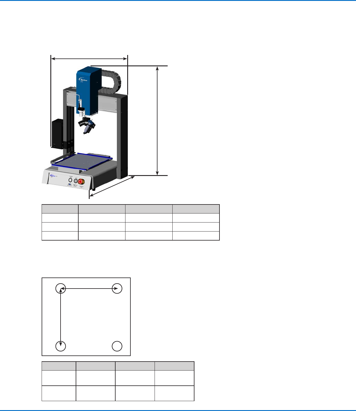
Technical Data
Dimensions
Dimension R3V R4V R6V
A (width) 645mm (25") 745mm (29") 965mm (38")
B (height) 914mm (36") 914mm (36”) 914mm (36”)
C (depth) 552mm (22") 652mm (26") 752mm (30")
Robot Feet Mounting Hole Template
Use these dimensions to drill mounting holes for the robot feet.
Dimension R3V R4V R6V
A
400mm
(15.75")
500mm
(19.69")
500mm
(19.69")
B
410mm
(16.14")
510mm
(20.08")
510mm
(20.08")
C
B
A
4 x M5 tapped holes
B
A
RV Series Automated Dispensing Systems
95www.nordsonefd.com info@nordsonefd.com +1-401-431-7000 Sales and service of Nordson EFD dispensing systems are available worldwide.
Maximum Voltage Maximum Current
125 VAC 15A
250 VAC 10A
28 VDC 8A
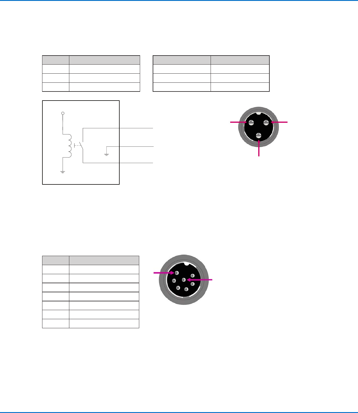
Pin# Description
1 NOM (Normally open)
2 COM (Common)
3 EARTH (Ground)
2
1 3
Pin 1
Pin 2
Pin 3
+24V
Relay
Ext. Control Port
NOTES:
• Inputs are not polarity-sensitive.
• The optional start / stop box accessory facilitates input / output connections to this port. Refer to “Start / Stop
Box” on page92 for part numbers.
Pin Description
1 Ground
2 Start signal
3 Motor power
4 Motion idle
5 Run / Teach
6 Emergency stop
7 Emergency stop
1
7
Technical Data (continued)
Wiring Diagrams
Dispenser Port

RV Series Automated Dispensing Systems
96 www.nordsonefd.com info@nordsonefd.com +1-401-431-7000 Sales and service of Nordson EFD dispensing systems are available worldwide.
I/O Port
NOTES:
• Outputs are rated at 125 mA.
• Courtesy +24 VDC output is rated at 3.0 Amp.
Pin Description Pin Description Pin Description
1 Input 1 10 Not connected 19 Output 6
2 Input 2 11 GND 20 Output 7
3 Input 3 12 GND 21 Output 8
4 Input 4 13 GND 22 Not connected
5 Input 5 14 Output 1 23 Not connected
6 Input 6 15 Output 2 24 +24 VDC
7 Input 7 16 Output 3 25 +24 VDC
8 Input 8 17 Output 4
9 Not connected 18 Output 5
Input schematic Output schematic
Pin 25
Input X
+24V
Output X
Pin 13
+24V
Technical Data (continued)