Nordson_EFD_RV_Series_Operating_Manual.pdf - 第52页
RV Series Automated Dispensing Systems 52 www.nordsonefd.com info@nordsonefd.com +1-401-431-7000 Sales and service of Nordson EFD dispensing systems are available worldwide. Setting Up the System Using the Robot Initial …
RV Series Automated Dispensing Systems
51www.nordsonefd.com info@nordsonefd.com +1-401-431-7000 Sales and service of Nordson EFD dispensing systems are available worldwide.
Setting Up the System Using the Robot Initial Setup Wizard (continued)
Robot Initial Setup (Step1 Tab): Setting Up Tip Detection and Tool Centering Calibration
(continued)
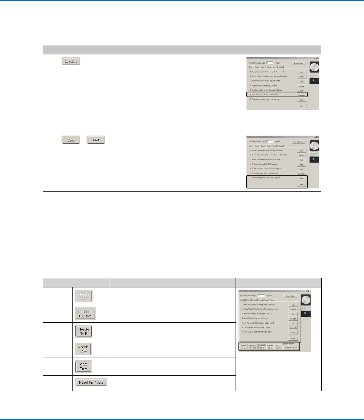
Function of the Test-Move Buttons in the Robot Initial Setup Wizard
Use the buttons at the bottom of the Robot Initial Setup window to verify settings at any time during the setup
process.
Button Function Reference Image
Needle
to C
Moves the tip to the calibration point that was
2mm above the tip detection device.
Needle to
B-5mm
Moves the tip to 5mm above the point used for
the tool centering calibration.
Needle
to B
Moves the tip to the point used for the tool
centering calibration.
Needle
to A
Moves the tip to the test deposit location.
CCD to A Centers the camera over the test deposit location.
Reset the
4 Axis
Resets the tool centering calibration calculation.
# Click Step Reference Image
7
• Click CALCULATE.
The system performs the tool centering
calibration. This calibration ensures that the
tip stays centered over the same point while
rotation occurs, even as the X and Y axes
adjust the location of the workpiece.
NOTE: To test the setup, use the buttons at
the bottom of the wizard. Refer to “Function
of the Test-Move Buttons in the Robot
Initial Setup Wizard” below for detailed
information.
8
>
• Click SAVE.
• Click NEXT.
9 • Continue to “Robot Initial Setup (Step2
Tab): Setting the Camera-to-Tip Offset” on
page52.
RV Series Automated Dispensing Systems
52 www.nordsonefd.com info@nordsonefd.com +1-401-431-7000 Sales and service of Nordson EFD dispensing systems are available worldwide.
Setting Up the System Using the Robot Initial Setup Wizard (continued)
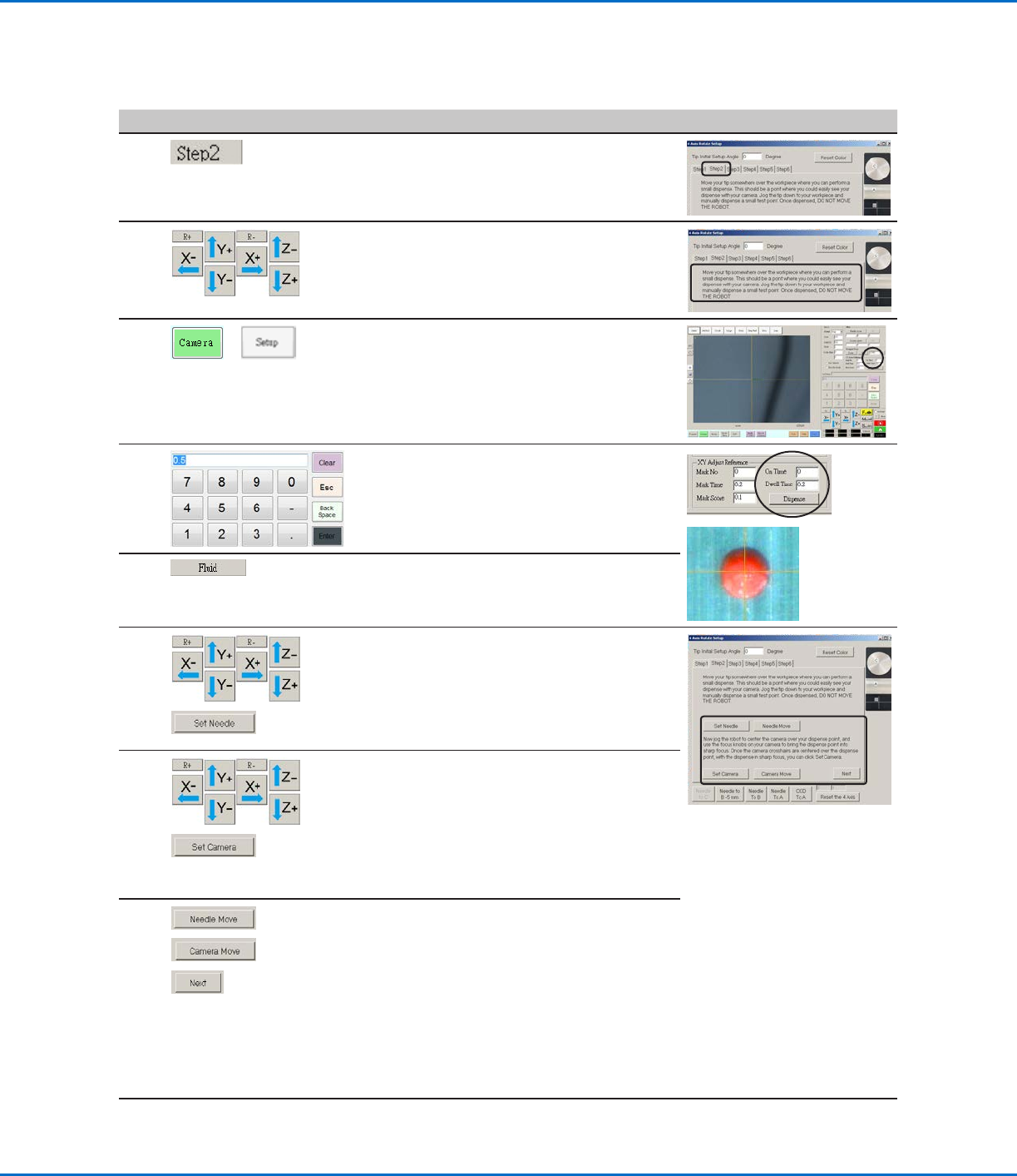
Robot Initial Setup (Step2 Tab): Setting the Camera-to-Tip Offset
# Click Step Reference Image
1
• Ensure that the STEP2 tab is open.
2
• Jog the tip to a good location on the work
surface to deposit a test dot of fluid.
3
>
• Click the CAMERA tab and then click SETUP
at the top of the Camera screen.
You will use the fields under XY Adjust
Reference to deposit a test dot of fluid.
4
• Use the keypad to enter the following
recommended dispense dot parameters:
- ON TIME: 0.5
- DWELL TIME: 0.2
5
• Click FLUID to dispense a dot of fluid.
6
>
• Jog the tip until it is positioned about 2mm
above the dispense dot.
• Click SET NEEDLE.
7
>
• Jog the camera until the camera crosshairs
are centered over the dispense dot.
• Focus the camera until the image of the
dispense dot is clear. Refer to “Camera” on
page16 as needed for instructions on
focusing the camera.
• Click SET CAMERA.
8
>
• Click NEEDLE MOVE to test the setup.
The system should deposit a dispense dot
at the same dispense location used for
step5.
• Click CAMERA MOVE to further test the
setup.
The camera should center its crosshairs
over the test dot dispensed in step 5.
• Click NEXT.
9
• Continue to “Robot Initial Setup (Step3
Tab): Setting a Mark” on page53.
RV Series Automated Dispensing Systems
53www.nordsonefd.com info@nordsonefd.com +1-401-431-7000 Sales and service of Nordson EFD dispensing systems are available worldwide.
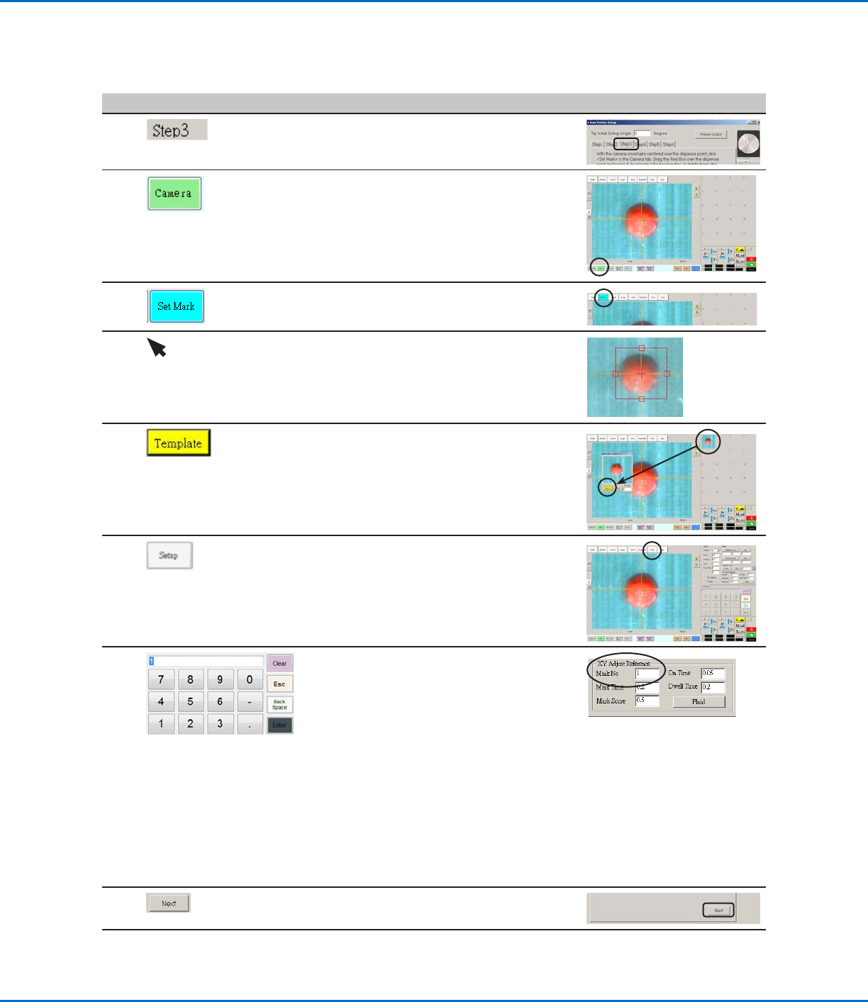
Robot Initial Setup (Step3 Tab): Setting a Mark
# Click Step Reference Image
1
• Ensure that the STEP3 tab is open.
2
• Click the CAMERA tab.
The actual camera view appears in the
Primary View screen and the Mark Library
appears in the Secondary View screen.
3 • Click SET MARK.
A red box appears.
4 • Click and hold the center of the red box,
drag it over the dispense dot, and then click
and drag the four box handles such that
they outline the dot.
5
• Click a socket in the Mark Library to save the
mark as a Mark No., then click TEMPLATE
when the Template Match window appears.
The system saves the image in the Mark
Library.
NOTE: Be sure to remember the Mark No.
6
• Click SETUP to go back to the Camera
window Offset fields.
7
• Use the keypad to enter the Mark number
in the Mark No field under XY Adjust
Reference.
NOTES:
- Make sure you click ENTER on the keypad
to enter the Mark number.
- Mark Time sets the time allowed for the
system to find the mark.
- Mark Score specifies how accurately the
camera finds a mark based on a value
from 0.1 to 1. A higher value results in
more precise matching. A lower value
results in less precise matching.
8
• Click NEXT.
9 • Continue to “Robot Initial Setup (Step4
Tab): Setting the Camera Scale” on
page54.
Setting Up the System Using the Robot Initial Setup Wizard (continued)