Nordson_EFD_RV_Series_Operating_Manual.pdf - 第40页
RV Series Automated Dispensing Systems 40 www.nordsonefd.com info@nordsonefd.com +1-401-431-7000 Sales and service of Nordson EFD dispensing systems are available worldwide. Camera Setup Scr een Click the CAMERA SETUP ta…
RV Series Automated Dispensing Systems
39www.nordsonefd.com info@nordsonefd.com +1-401-431-7000 Sales and service of Nordson EFD dispensing systems are available worldwide.
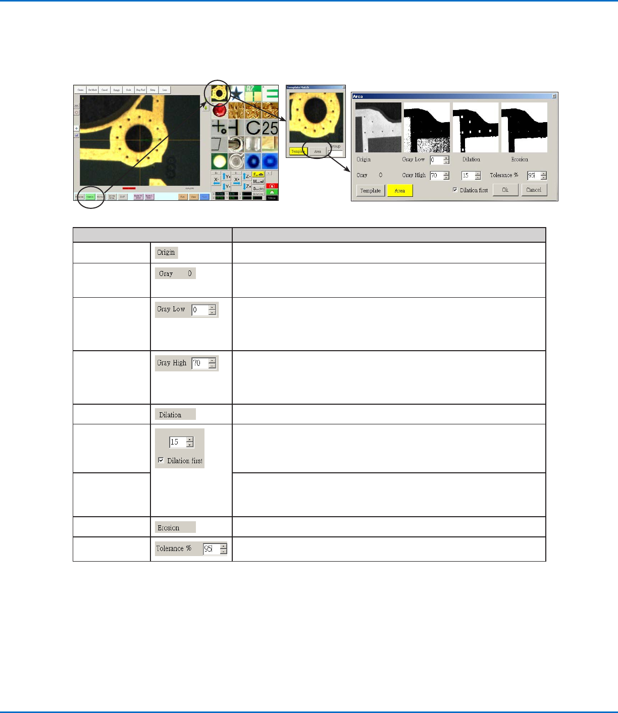
Template Match and Area Windows
Once a mark is stored in the Mark Library, you can right-click on the mark image cell and select PROPERTY to open
the Template Match window. The Template Match window provides access to the Area window, which is used to
fine-tune how the camera evaluates a mark.
Template Match Area Window Section Function
Origin
Displays the open mark image.
Gray Displays the gray rating for the selected point in the original image. When a point is
selected, the value changes to reflect the gray level at that point. Knowing this value
makes it easier to determine the best Gray Low and Gray High values to set.
Gray Low
Adjusts the gray low-tolerance value. The lower the value, the more white is
tolerated in the image. The higher the value, the less white is tolerated in the image.
NOTE: Gray Low values are typically lower than Gray High values.
Range: 0–255
Gray High
Adjusts the gray high-tolerance value. The lower the value, the less white is tolerated
in the image. The higher the value, the more white is tolerated in the image.
NOTE: Gray High values are typically higher than Gray Low values.
Range: 0–255
Dilation Displays how the image appears after the Dilation calculation.
Dilation First
counter
When Dilation First is checked, the counter above the Dilation First checkbox
controls the zoom of the image. When Dilation First is unchecked, the counter
controls how much of the non-gray areas in the image are ignored.
Range: 0–20
Dilation First
checkbox
Sets the order in which the dilation and erosion calculations are performed. If the
Dilation First checkbox is checked, the system performs the dilation calculation first.
If the checkbox is unchecked, the system performs the erosion calculation first.
When Dilation First is unchecked, the Dilation and Erosion labels switch places.
Erosion
The image above Erosion shows how much white is filtered from the image.
Tolerance Sets the tolerance for how similar other mark images can be to the selected image,
allowing the system to eliminate similar marks.
RV Series Automated Dispensing Systems
40 www.nordsonefd.com info@nordsonefd.com +1-401-431-7000 Sales and service of Nordson EFD dispensing systems are available worldwide.
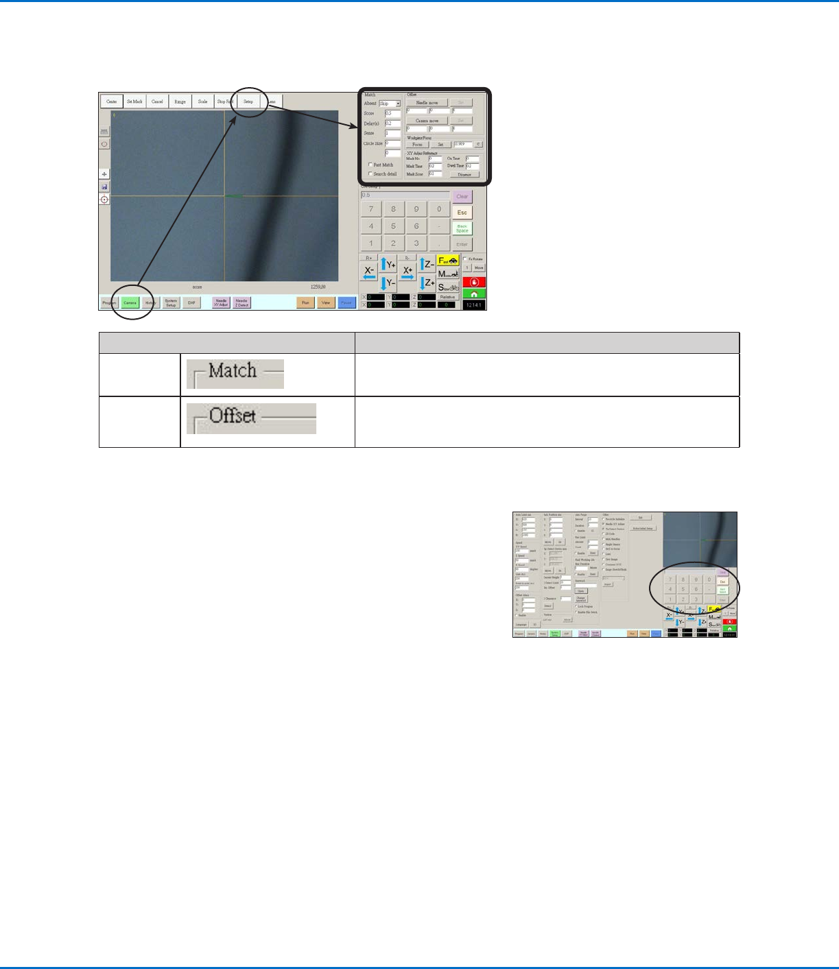
Camera Setup Screen
Click the CAMERA SETUP tab to see the Camera setup fields. The actual view of what the camera sees appears in
the Primary View screen and the camera setup fields appear in the Secondary View screen.
Camera Screen Setup Window Section Function
Match
Affects how the camera searches for marks. Refer to “Setting How
the System Finds Marks (Optional)” on page59.
Offset
Used only as needed for manual calibration of the tip-to-camera
offset in place of using the Robot Initial Setup wizard. Refer to
“AppendixB, Non-Wizard Setup Procedures” on page124.
Keypad
A numeric keypad appears when data entry fields are present.
Use the keypad for mouse-click entry of numbers as an
alternative to using the numbers on the keyboard. Regardless of
how numbers are entered, you must select Enter (on the keypad
or the keyboard) for the system to accept the input.
RV Series Automated Dispensing Systems
41www.nordsonefd.com info@nordsonefd.com +1-401-431-7000 Sales and service of Nordson EFD dispensing systems are available worldwide.
Setup
After installation and before creating any programs, perform these required and optional setup procedures as
applicable for your automated dispensing system.
Setting System Parameters
The factory system settings are appropriate for most applications. Use this procedure as needed to view or change
system settings. Important system settings include the following:
• Speed: The speed at which the dispensing tip moves.
• Line Acc: How the robot accelerates from one point to another.
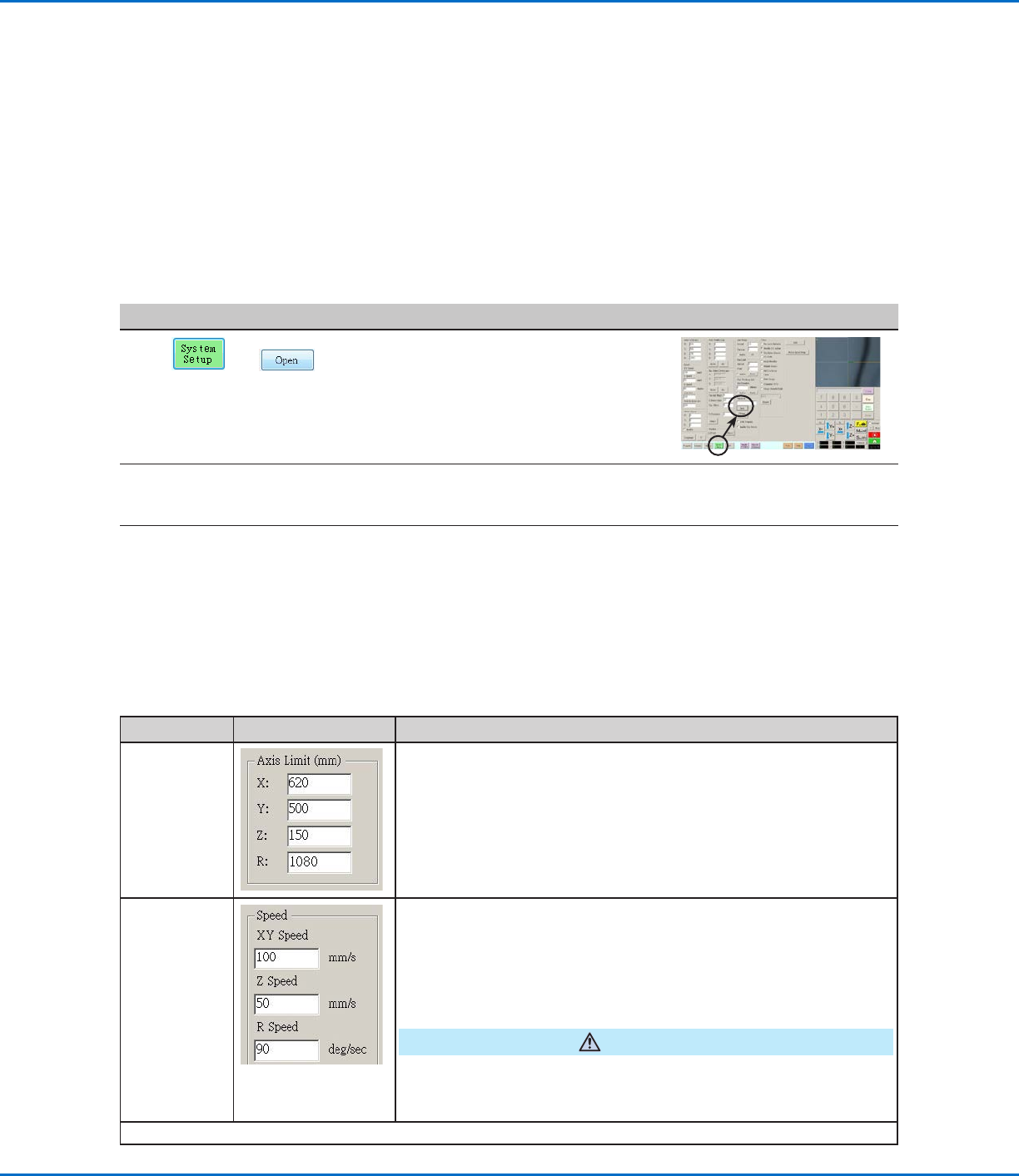
To View or Change System Parameters
#
Click Step Reference Image
1
>
• Click the SYSTEM SETUP tab, then click
OPEN.
2 • View or change parameters as appropriate for your application. Refer
to “System Setup Screen Fields” below for information on system-level
parameters.
3
• Click another tab to close the System Setup screen.
NOTE: Settings are automatically saved except for the Model and Language
selections. Changes to these selections take effect after you EXIT and reopen
the DispenseMotion software.
System Setup Screen Fields
NOTE: Default values may vary depending on the selected robot model.
Item Screen Capture Description
Axis Limit
Sets the range limits within which the robot can move. A value higher
than the default settings cannot be entered.
Speed
Sets the speed (inmm/s) of the axis movement. For maximum speed
specifications, refer to “Specifications” on page12.
NOTE: You can also change the jog speed settings by clicking the 2 next
to the navigation and jogging window. Refer to “Navigation and Jogging
Window” on page34 for detailed information.
CAUTION
The robot automatically adjusts its speed depending on the complexity
of the pattern. Forcing the robot to run at higher speeds can compromise
accuracy and may disrupt system operation.
Continued on next page