Nordson_EFD_RV_Series_Operating_Manual.pdf - 第19页
RV Series Automated Dispensing Systems 19 www.nordsonefd.com info@nordsonefd.com +1-401-431-7000 Sales and service of Nordson EFD dispensing systems are available worldwide. Position the Robot and Install and Connect Com…
RV Series Automated Dispensing Systems
18 www.nordsonefd.com info@nordsonefd.com +1-401-431-7000 Sales and service of Nordson EFD dispensing systems are available worldwide.
Position the Robot and Install and Connect Components
Refer to the Quick Start Guide and to this section as needed to install the system components and make
connections.
NOTES:
• The components of an automated dispensing system vary. Steps for a complete system with all available
components are provided in this manual and in the Quick Start Guide. Perform only the steps that apply to your
system.
• If the system is being used in the European Community, the robot is shipped with an enclosure or light curtain
that (1) prevents an operator from entering the robot’s work area and (2) generates an emergency stop signal if the
enclosure door switch is opened while the robot is running.
Applicability Item
Components to Install
or Connect
Installation Tasks
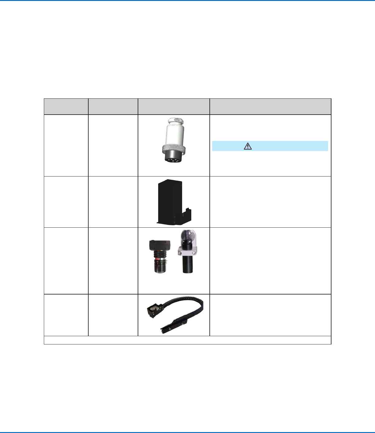
All models Input/output
safety plug
(SHORTED)
Connect the input/output safety plug to the
Ext. Control port to bypass the door switch.
CAUTION
Install this plug only if you want to bypass the
door switch. When this plug is installed, the
customer assumes all safety liability.
All models DispenseMotion
controller
Mount the DispenseMotion controller on
the shelf.
Install the shelf-and-controller assembly on
the left upright bracket.
Make the connections shown on the Quick
Start Guide.
All models CCD camera
Fixed-
mount
R-mount
(Optional for the fixed-mount camera only)
Install the provided optional lenses.
Install the camera and bracket assembly.
Connect the camera cable to the camera.
Route the camera cable through the dragon
chain on the Z axis.
Connect the cable to USB-CCD on the
DispenseMotion controller.
All models Tip detector or tip
aligner (optional)
Install the tip detector or tip aligner.
Connect the cable to the Tactile port on the
back of the robot.
Continued on next page
RV Series Automated Dispensing Systems
19www.nordsonefd.com info@nordsonefd.com +1-401-431-7000 Sales and service of Nordson EFD dispensing systems are available worldwide.
Position the Robot and Install and Connect Components (continued)
Applicability Item
Components to Install
or Connect
Installation Tasks
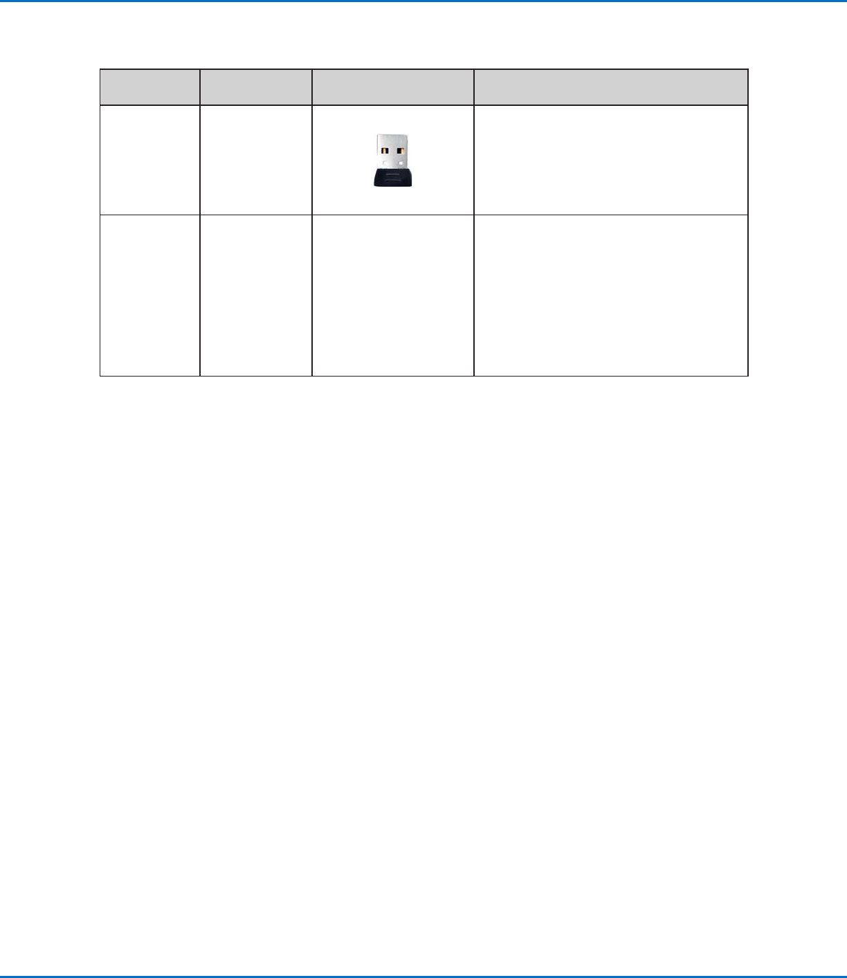
All models Monitor,
keyboard, and
mouse (not
shown); dongle
for wireless
keyboard and
mouse
Connect the monitor.
Connect the wireless keyboard and mouse
dongle to USB 4 on the DispenseMotion
controller.
All models Dispenser
components
As applicable
Mount the syringe barrel or dispensing
valve holder (as applicable) on the Zaxis;
choose mounting holes that allow a
maximum workpiece clearance but also
allow the dispensing tip to reach all areas
on the workpiece where dispensing is
required.
Refer to the dispensing equipment manuals
for all other dispensing system installation
steps.
RV Series Automated Dispensing Systems
20 www.nordsonefd.com info@nordsonefd.com +1-401-431-7000 Sales and service of Nordson EFD dispensing systems are available worldwide.
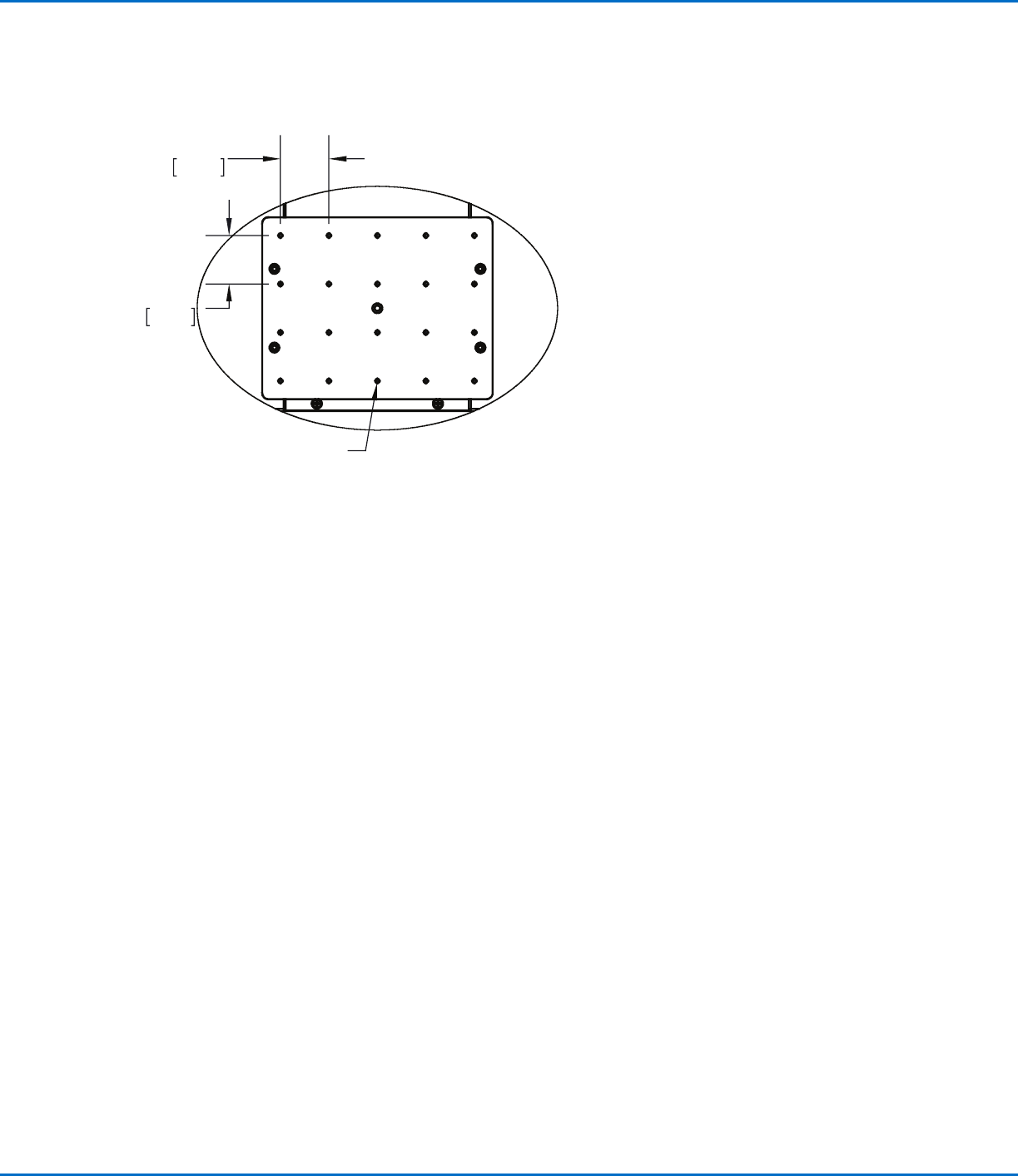
Prepare the Work Surface or Fixture Plate
Prepare the robot work surface or fixture plate for secure placement of the workpiece. Refer to “Fixture Plates” on
page92 for fixture plate part numbers. A fixture plate mounting hole template is provided below.
Connect Inputs / Outputs (Optional)
All automated dispensing systems provide 8 standard inputs and 8 standard outputs. Connect input / output
wiring to the I/O PORT connection on the back of the robot. For a wiring diagram, refer to “I/O Port” on page96.
There are several ways to use the system inputs / outputs. Refer to “Setting Up Inputs / Outputs” on page58 for
additional information on inputs / outputs.
300 x 300, 400 x 400, or 600 x 600 fixture plate
1.57
40.00
1.57
40.00
M4X0.7 - 6H THRU ALL