Nordson_EFD_RV_Series_Operating_Manual.pdf - 第64页
RV Series Automated Dispensing Systems 64 www.nordsonefd.com info@nordsonefd.com +1-401-431-7000 Sales and service of Nordson EFD dispensing systems are available worldwide. Setting the Tip Rotation Angle in the CCD Mode…
RV Series Automated Dispensing Systems
63www.nordsonefd.com info@nordsonefd.com +1-401-431-7000 Sales and service of Nordson EFD dispensing systems are available worldwide.
How to Rotate the Tip and Set the Angle of Rotation (continued)
Setting the Tip Rotation Angle in the Tip Mode
Follow this procedure to physically rotate the tip to the desired angle of rotation.
Important: The tip will not rotate, either virtually or physically, until the tool centering calibration portion of
the Robot Initial Setup wizard has been performed. This calculation is Step 1 of the wizard.
PREREQUISITES
The system is properly set up. Refer to “Setting Up and Calibrating the System (Required)” on page45.
# Click Step Reference Image
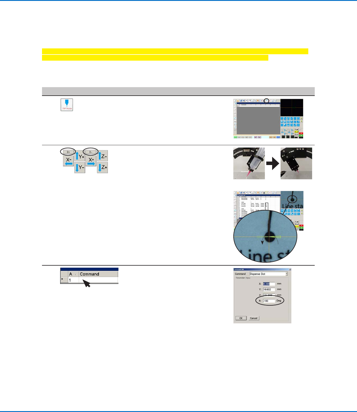
1
• Click the MODE icon to place the system
in the Tip mode.
NOTE: When the system is in the Tip
mode, the dispense valve and tip installed
on the Zaxis head will rotate; the green
arrow on the camera view screen will also
rotate.
2 • Click R+ to rotate the tip clockwise.
• Click R- to rotate the tip
counterclockwise.
Observe the dispense valve on the robot
Zaxis head to see the rotation, or
observe the green arrow in the Secondary
View screen to see the tip rotation.
0°-180°
3 • Double-click a command address line to
open the command edit drop-down menu
and then open the desired command.
The system automatically populates the
Rfield with the current angle of rotation.
In addition, the values in column 4 of the
command address lines show the tip
rotation angle. Refer to “DispenseMotion
Screen Elements Used to Show Tip
Rotation” on page62 for an illustration.
RV Series Automated Dispensing Systems
64 www.nordsonefd.com info@nordsonefd.com +1-401-431-7000 Sales and service of Nordson EFD dispensing systems are available worldwide.
Setting the Tip Rotation Angle in the CCD Mode
Follow this procedure to rotate the tip virtually (not physically) to the desired angle of rotation by viewing the green
arrow on the camera view screen.
Important: The tip will not rotate, either virtually or physically, until the tool centering calibration portion of
the Robot Initial Setup wizard has been performed. This calculation is Step 1 of the wizard.
PREREQUISITES
The system is properly set up. Refer to “Setting Up and Calibrating the System (Required)” on page45.
# Click Step Reference Image
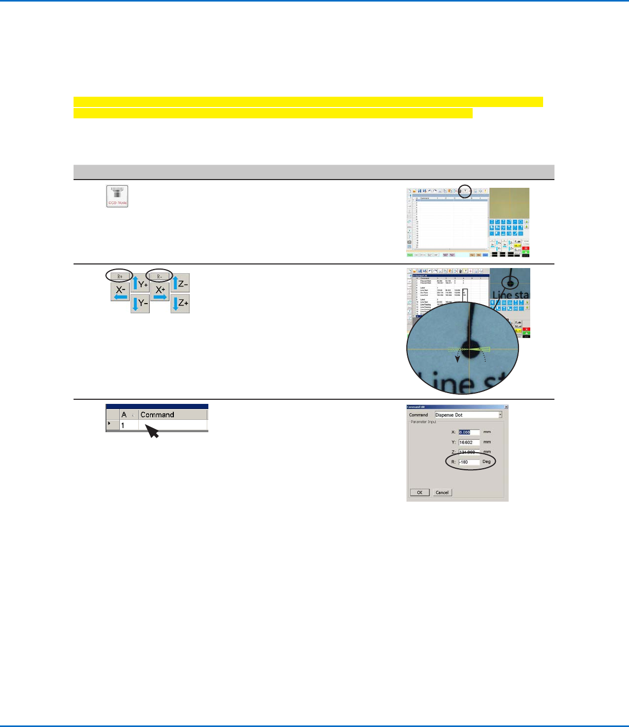
1
• Click the MODE icon to place the system
in the CCD mode.
NOTE: When the system is in the CCD
mode, the dispensing valve installed on
the Zaxis head will NOT rotate.
2 • Click R+ to rotate the tip clockwise.
• Click R- to rotate the tip
counterclockwise.
Observe the green arrow on the
Secondary View screen to see the tip
rotation.
0°-180°
3 • Double-click a command address
line to open the command edit drop-
down menu and then open the desired
command.
The system automatically populates the
R field with the current angle of rotation.
In addition, the values in column 4 of the
command address lines show the tip
rotation angle. Refer to “DispenseMotion
Screen Elements Used to Show
Tip Rotation” on page62 for an
illustration.
How to Rotate the Tip and Set the Angle of Rotation (continued)
RV Series Automated Dispensing Systems
65www.nordsonefd.com info@nordsonefd.com +1-401-431-7000 Sales and service of Nordson EFD dispensing systems are available worldwide.
How to Create and Run a Program
The procedure provides the basic steps for creating and running a program. Every program is different. Use these
basic steps and refer to “How to Create Patterns” on page68 and “AppendixA, Command Function Reference”
on page98 to create the desired application pattern for the workpiece or group of workpieces.
PREREQUISITES
The system is properly set up. Refer to “Setting Up and Calibrating the System (Required)” on page45.
If the tip or any element of the Zaxis head was changed, repeat system setup and calibration using the Robot
Initial Setup wizard. Refer to “Setting Up the System Using the Robot Initial Setup Wizard” on page48.
The system is in the correct mode (Tip or CCD).
A workpiece is properly positioned on the fixture plate.
# Click Step
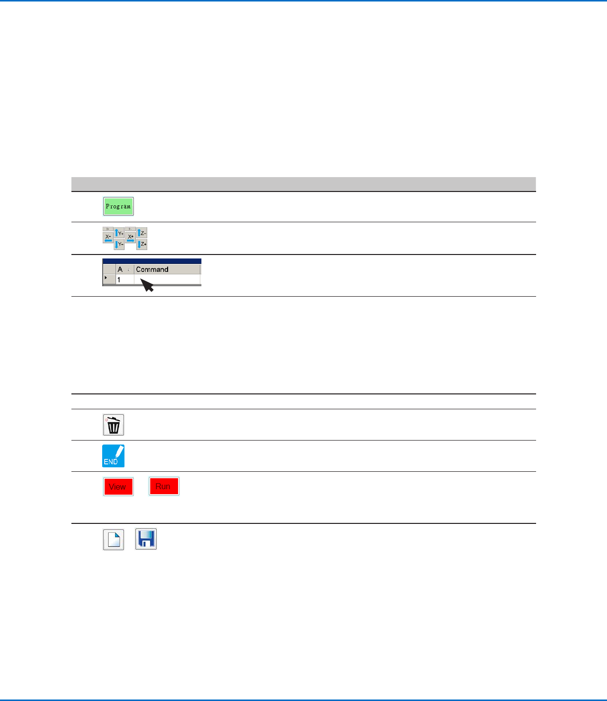
1
• Click the PROGRAM tab.
Address 1 is available to insert a command.
2
• Jog the dispensing tip to a desired XYZR location by clicking the navigation
icons.
3
• Insert a setup or dispense command that tells the robot what to do. Click
a command icon, or double-click anywhere in the address line to select a
command from the drop-down menu.
4
• Edit the command parameter settings. Refer to the following sections of this
manual for information to help you create programs:
- “About Programs and Commands” on page22 (includes best practices)
- “How to Create Patterns” on page68
- “How to Create a Mark” on page72
- “AppendixA, Command Function Reference” on page98 (provides
detailed information on all commands)
5
• Repeat steps 2 through 4 until the program is complete.
6
• To delete a command, click the command and then click the Delete icon.
7
• Click END PROGRAM to end the program.
8
or
• Click VIEW or RUN to test the program and make adjustments until the
program runs correctly.
NOTE: VIEW runs a program by tracing it with the camera, without
dispensing fluid. RUN runs the actual program, including dispensing
9
>
• Click A NEW FILE.
• Click SAVE. If the file is not already named, enter a name for the file.
• Click YES/OK when prompted for confirmations.